We use the details you submit to review and respond to your project enquiry. Entries are handled in this website’s WordPress database using Fluent Forms; our hosting and email providers may process the submitted details. Other technical providers receive only the data described in our Privacy Policy.
Please do not send passwords, payment-card details, government identification numbers, sensitive personal data, or unnecessary confidential third-party information.
Updated October 2026 · Reviewed by the Storm Manage technical team
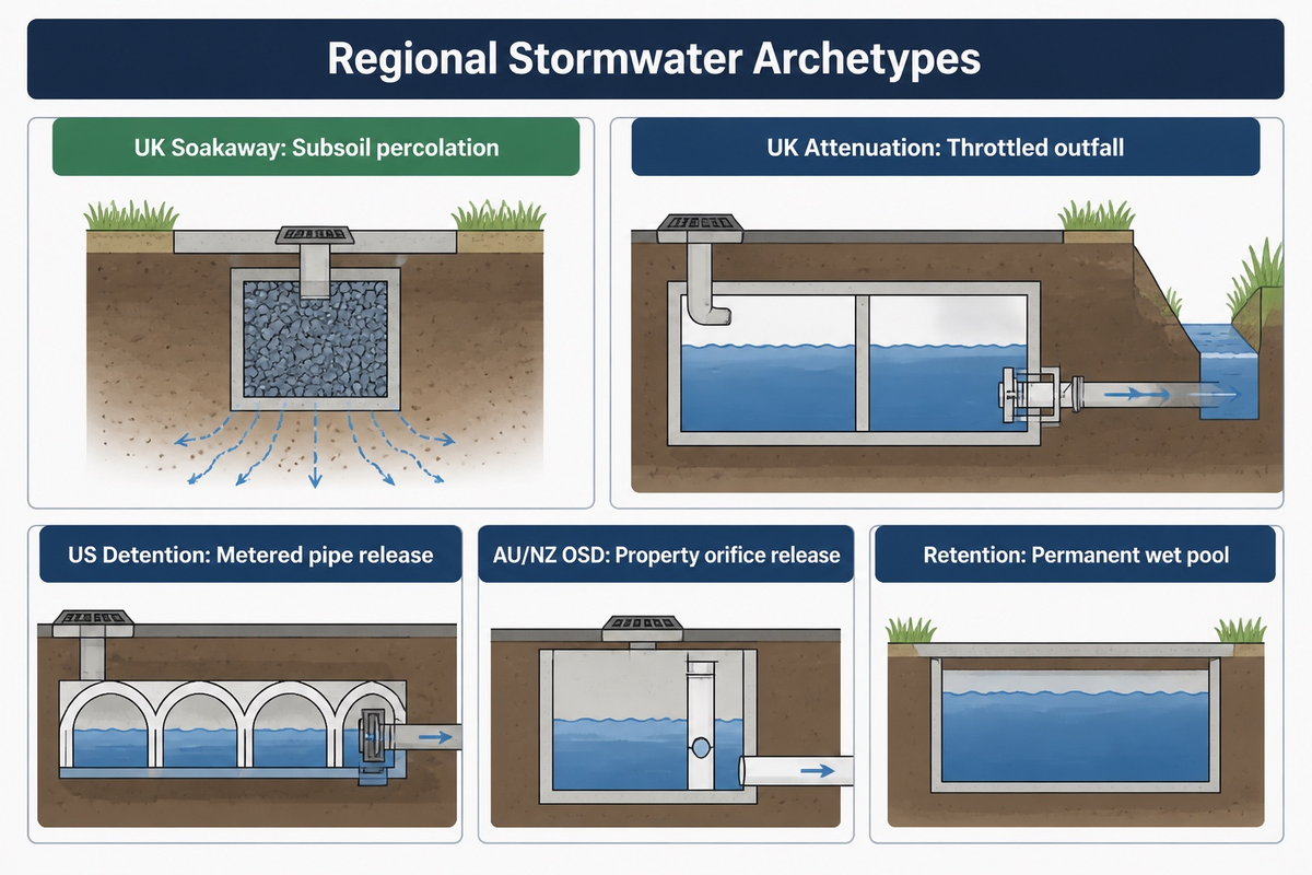
In terms of soakaway vs attenuation vs detention vs osd, a standalone soakaway disposes of runoff primarily by ground infiltration (however, an exceedance overflow may be included). On the other hand, UK attenuation, US detention and Australian On-Site Stormwater Detention (OSD) describe controlled-release storage that holds runoff above or below ground and/or within dual-purpose partial-infiltration systems and meters outflow.
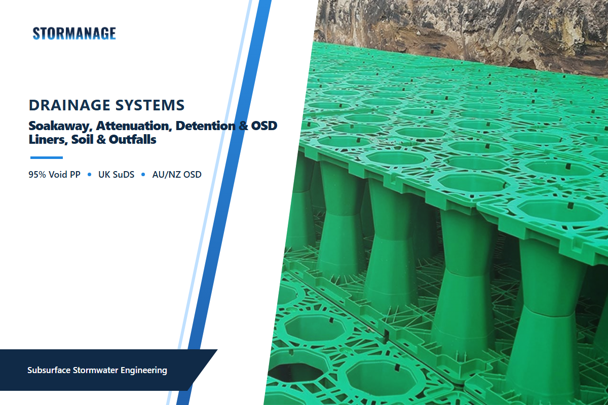
Civil engineers and groundwork buyers frequently assess drawings from various jurisdictions that specify interlocking polypropylene crates under local regulatory terms. On Storm Manage’s published ST-series modular crate specifications, a 95%-void geocellular matrix wrapped by a permeable geotextile allows infiltration into surrounding suitable soil, while an impermeable geomembrane retains the water, so a downstream outlet can be placed to control flow and release.
Quick Engineering Reference: Hydraulic Pathways Across Regional Standards
In the Buckinghamshire Lead Local Flood Authority (LLFA) guidance, standalone soakaways without a routine base outlet require field infiltration of at least 1 × 10⁻⁶ m/s (while Type B partial-infiltration systems discharging to a suitable drainage-hierarchy receptor can operate down to 1 × 10⁻⁸ m/s), unsaturated clearance above seasonal high groundwater verified over the local wettest water-table window, and half-empty drawdown within 24 hours for catchments over 100 m², as per Shropshire Council’s BRE Digest 365 guidance.
Controlled-release storage pairs an outlet flow regulator with project-specific discharge or drawdown rules: England’s 2025 Defra SuDS Standards cap 50% Annual Exceedance Probability (AEP) peak outflow at the greater of the greenfield runoff rate or 3 L/s/ha, Philadelphia’s subsurface detention manual sets a 72-hour maximum drain time and ≤10⁻⁸ m/s liner permeability, and Hornsby Shire Council OSD submittals specify Permissible Site Discharge (PSD) and Site Storage Requirement (SSR).
Retention systems (US/UK wet ponds or rainwater harvesting cisterns) hold a permanent water pool for settling of biological pollutants or non-potable reuse instead of draining dry between storms.
Storm Manage’s ST-series modules provide 95% internal void space (237.5 L net per 250 L 500 mm crate) versus 40% crushed-stone porosity in Philadelphia’s manual; in our worked example below, 220 crates (52.25 m³ net storage) with 150 mm bedding, 300 mm side-fill, and 800 mm cover require a 126.7 m³ trench, or 2.42 times installed net storage.
Soakaway vs Attenuation vs Detention vs OSD at a Glance
Across international drainage drawings, soakaway, attenuation, detention, and OSD are not four rigid product shapes; they denote regional regulatory terms for infiltration disposal and controlled-release storage (which can also overlap in hybrid partial-infiltration designs). A standalone soakaway recharges permeable ground without a routine low-level outlet pipe, while attenuation, detention, and OSD hold storm runoff in surface or subsurface storage and throttle release.
Impermeable geomembrane between protective fleeces
Impermeable liner (≤10⁻⁸ m/s in PWD) or rigid vault
Impermeable lined crate matrix or concrete tank
Watertight liner with sealed base or clay wet basin
Outlet Pipe & Throttle
No routine low-level discharge pipe (high-level exceedance overflow where specified)
Base outlet to vortex flow control or orifice plate
Low-level orifice, weir, or multi-stage riser pipe
Discharge Control Pit (DCP) with screen and orifice
No base drain orifice; pump draw-off + high overflow
Soil Infiltration Need
≥1 × 10⁻⁶ m/s standalone (Buckinghamshire LLFA)
No soil infiltration required (suits heavy clay)
No infiltration required when lined in urban soils
Lined OSD does not rely on soil infiltration
Low-permeability soil or liner retains permanent pool
Example Governing Guidance
Approved Document H (H3), BRE Digest 365, CIRIA C753
Defra 2025 SuDS Standards, CIRIA C753 / C737, DCG
US EPA NPDES framework & municipal manuals (e.g., PWD)
Council OSD handbooks (e.g., Hornsby), ARR 2019
US EPA Wet Pond BMP Fact Sheet & reuse codes
Release / Drawdown Target
Half empty within 24 hours (>100 m² catchments, BRE 365)
50% AEP capped at greater of greenfield rate or 3 L/s/ha (Defra)
72 hours max subsurface drawdown (PWD Ch. 4)
Metered to council PSD (L/s) with SSR (m³) storage
Permanent pool retained; storm surcharge drains out
Runoff Volume Reduction
High (infiltrates captured storm volume into ground)
Low in sealed tanks (cuts peak L/s flow, not volume)
Zero in watertight vaults (shaves hydrograph peak)
Zero in lined tanks (delays peak flow to trunk pipe)
Achieved when harvested water supplies site demand
Pretreatment & Access
Upstream silt trap needed to stop geotextile blinding
Upstream catchpit plus internal CCTV jetting channel
Mandatory inlet pretreatment (PWD) + inspection port
Upstream pit + removable trash screen inside DCP
Sediment forebay (wet pond) or fine pre-tank filter
Setback & Groundwater Check
≥5 m building/road offset (UK H3); unsaturated water-table clearance
Flotation check required where groundwater reaches tank
10 ft (3.05 m) offset in PWD unless self-supporting watertight concrete or FRP
Graded overland exceedance path + uplift check in wet ground
Embankment seepage check or buried cistern uplift slab
What are the different types of stormwater drainage systems?
Modern stormwater systems can be broken into four primary categories: infiltration systems (soakaways, permeable pavements, and infiltration trenches), dry detention and attenuation systems, wet retention systems (basins and rainwater cisterns), and conveyance (swales, ditches, and storm drains) systems.
Throughout an urban drainage basin, the majority of civils layouts incorporate more than one of these systems in a treatment train. Effective flood management pairs upstream conveyance channels and grit traps with infiltration crates, or lined attenuation storage on tight clay soils, protecting the receiving stream and public storm drain from surcharging. Controlling surface runoff at the plot boundary can minimize a development’s contribution to downstream channel erosion, and armored outfalls can limit local scour.
UK SuDS Comparison: Infiltration Soakaways vs Sealed Attenuation Tanks
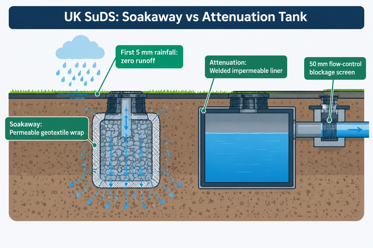
England’s June 2025 Defra Sustainable Drainage Standards place non-potable rainwater collection first and ground infiltration second ahead of piped waterbody or sewer outfalls; when trial-pit testing, high groundwater, foundation offsets, or ground contamination rule out standalone soakaways, engineers evaluate partial-infiltration layouts, surface SuDS, or sealed attenuation tanks.
Standard 1.2 of the 2025 UK National Standards for Sustainable Drainage Systems sets a five-tier runoff destination hierarchy for England alongside Building Regulations Approved Document H (Section H3), allowing multiple destinations in combination once higher-priority tiers have been used as far as reasonably practicable: Priority 1 collects rainwater for non-potable reuse, Priority 2 infiltrates runoff into the ground, Priority 3 discharges to a surface water body, Priority 4 discharges to a surface-water sewer, highway drain, or other piped drainage system, and Priority 5 connects to a combined sewer. Standard 2 further expects developments to manage the first 5 mm of everyday rainfall with zero surface runoff leaving the site.
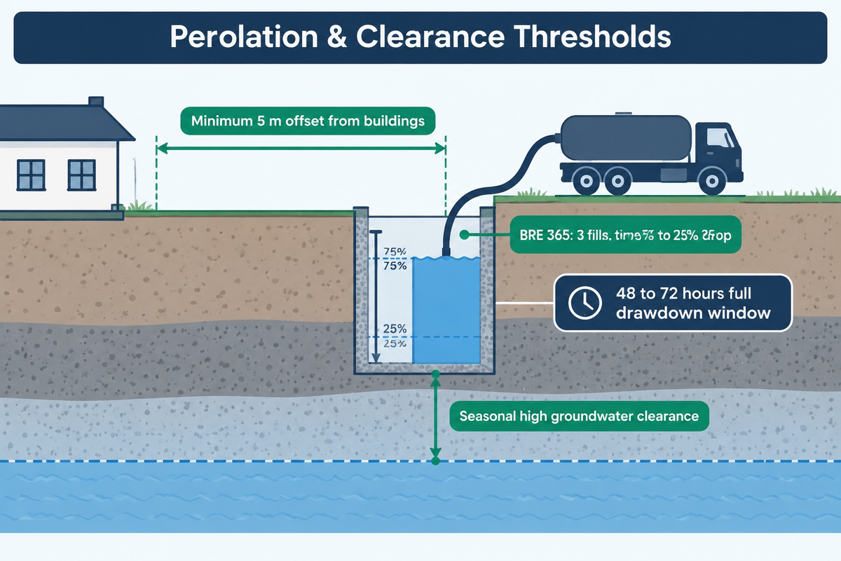
Lead Local Flood Authorities (LLFAs) challenge planning applications that propose underground geocellular attenuation tanks into a sewer without site percolation evidence showing why modular polypropylene soakaway crates or surface infiltration components can’t be used. Under Shropshire Council’s BRE Digest 365 soakaway design guidance, soakaways draining catchments larger than 100 m² must be designed from trial pits excavated below the proposed inlet invert to the full base depth of the soakaway and filled rapidly from a water bowser up to the proposed inlet invert, with standard BRE percolation testing repeating the fill three times and timing the drop from 75% to 25% effective storage depth using the slowest drop. Shropshire’s guide explicitly rejects filling trial pits from a garden hosepipe because slow inflow distorts the head-drop test.
What is the difference between an attenuation tank and a soakaway?
A soakaway reduces total runoff volume primarily by letting captured rainwater infiltrate into permeable surrounding ground (with an exceedance overflow where specified), whereas a sealed attenuation tank reduces peak flow rate by holding water inside an impermeable membrane and metering release into a watercourse or sewer via a flow control.
That functional split changes both hydraulic sizing and long-term asset adoption. Under BRE Digest 365 and Defra Table S3.1, infiltration designs apply a hydraulic factor of safety between 1.5 and 10 (scaled by catchment area below or above 1,000 m² and flood consequence) and require soakaways serving over 100 m² to drain half empty within 24 hours. Attenuated systems store extreme design storms including applicable regional climate-change rainfall allowances (Clause 3.8), with Clause 3.18 of England’s 2025 Defra SuDS Standards capping 50% AEP peak discharge at the greater of the greenfield runoff rate or 3 L/s/ha. Developers should also check utility adoption policies early: Storm Manage notes on its UK technical pages that while Water UK Design and Construction Guidance (DCG) governs adoptable sewer structures, some regional water companies such as United Utilities decline adoption of standalone plastic crate tanks used solely for storm attenuation, leaving maintenance with the property management entity.
US Detention vs Retention Systems and Australian/NZ OSD Rules
Within US municipal stormwater manuals implementing Clean Water Act NPDES programs, dry detention vaults and basins empty between storms (with a 72-hour maximum subsurface drain time in Philadelphia and a 72-hour dry-basin target noted by Rutgers as typical) while permanent water pools are kept in wet retention ponds; Australian Council OSD schedules set site PSD and SSR values.
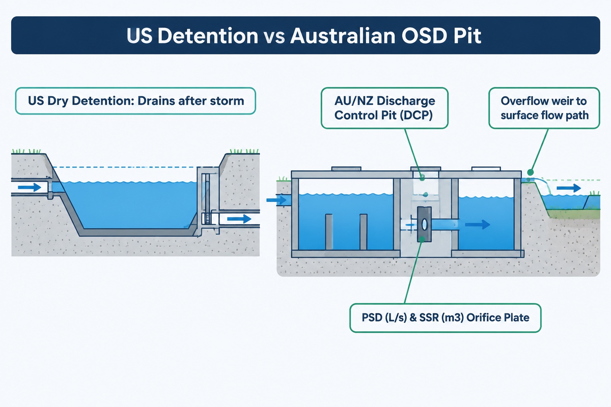
In US civil specifications, dry flood-peak storage is separated from permanent wet-pool treatment. As the US EPA Wet Ponds Stormwater BMP Fact Sheet documents, a wet retention basin is designed to keep a permanent pool of water, which allows suspended sediment to settle and nutrients to be taken up by vegetation and improve water quality for downstream users. Alternatively, subsurface stormwater detention tank systems drain after the event, and are designed to intercept and store pavement runoff (i.e. sheet flow) from parking lots and release it to downstream areas to aid in control of channel erosion. Required storage volumes depend highly on local conditions and regulations, and are illustrated in municipal detention storage rate rules, e.g. criteria in Harris County, Texas.
In Australia, On-Site Stormwater Detention (OSD) for peak flow attenuation is implemented at the property level, and is administered by Municipal Councils. In Hornsby Shire Council’s On-Site Detention Guidelines in New South Wales, the design of a stormwater detention system requires certification by a Chartered Professional Engineer, who defines the Permissible Site Discharge (PSD) in L/s, the Site Storage Requirement (SSR) in m³, and provides evidence of an orifice plate, maintenance schedule, and a permanent identification plate. In dual-purpose Australian OSD layouts, if rainwater harvesting is integrated with stormwater detention, then the Stormwater Detention tank must be sized for storage to fulfill both functions (with dedicated detention air space) to accommodate peak wet storage volume unless council-permitted demand drawdown offsets apply. Civil works must provide an overland flow path for storm water exceeding the tank’s design capacity.
What is the purpose of an OSD tank?
An OSD tank captures roof, driveway, and commercial pavement runoff within the property boundary and meters release through a calibrated orifice plate or vortex regulator to meet the council’s Permissible Site Discharge (PSD) limit for specified design storms, paired with an overland overflow route for extreme exceedance events.
For Australian developments, control of downstream discharge focuses on the Discharge Control Pit (DCP). In this system, stored stormwater builds hydraulic head behind a machined stainless steel orifice plate protected by a removable mesh trash screen, which meters discharge to the municipal street drain. An overflow weir directs surcharge to a safe, suitable surface flow path. A calibrated flow control, paired with a subsurface crate liner, operates in a downstream structure.
How Liners and Flow Controls Configure Geocellular Crate Assemblies
The same polypropylene crate matrix used for the above systems can be employed for infiltration or controlled release storage in the UK or US and Australia (OSD). The configuration selector below also shows a separate rainwater harvesting system.
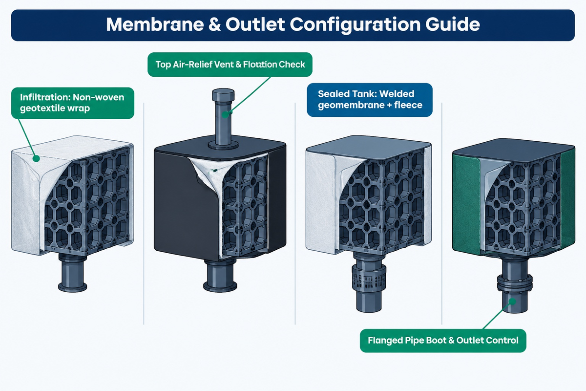
Failures during groundwork occur when geosynthetic wraps are treated as identical sheets. Under Sections 4.8.3 and 4.12 of the Philadelphia Water Department Stormwater Plan Review Manual Chapter 4, impervious liners enclosing subsurface detention must achieve a permeability of 10⁻⁶ cm/sec (10⁻⁸ m/s) or less, and every inlet must receive upstream pretreatment (such as sumps with trapping hoods, downstream trench-drain structures, or vegetated filter strips) before entering the storage structure. Storm Manage’s published geomembrane wrapping, venting, and manifold installation details describe impermeable geomembranes sandwiched between protective non-woven geotextile fleeces to reduce stone puncture risk; thermoplastic HDPE and LLDPE liners use thermally wedge-welded seams (allowing dual-track air-channel pressure testing on double-wedge seams and vacuum-box testing on extrusion details), whereas conventional cured EPDM membranes use compatible seam-tape or adhesive bonding systems.
Watertight wraps require air relief and groundwater uplift checks as well. If heavy rain surges into a sealed membrane crate block that lacks a top-mounted air exhaust vent routed to an unsubmerged chamber or cowl, trapped air pockets compress beneath the roof slab and restrict inflow even while storage capacity remains unused. However, Buckinghamshire Council’s LLFA SuDS component standards state that flotation analysis should be carried out for sealed tanks where groundwater can rise and exert an upward, buoyant force on an empty chamber.
The Membrane-and-Outlet Configuration Selector
Membrane-and-Outlet Configuration Selector for Modular Polypropylene Crates
Overlapped or tacked fabric joints; collared inlet pipe entry
Air vents through permeable wrap or dedicated breather pipe
No base discharge pipe; crate vendor supplies PP modules + geotextile
UK Attenuation / US Detention
Impermeable geomembrane (≤10⁻⁸ m/s in PWD) cushioned by inner/outer protective geotextile fleece
Thermal wedge welds on HDPE/LLDPE (or adhesive tape on EPDM); sealed flanged pipe boots
High-level air exhaust vent sized to peak inflow to prevent air-locking
Base outlet feeds civil contractor’s downstream manhole with vortex valve or orifice
Australian OSD Setup
Impermeable geomembrane between protective fleeces (or rigid tank)
Tested watertight seams plus sealed inlet, outlet, and vent penetrations
High-level vent piped to atmosphere above flood surcharge level
Connects to civil-built DCP housing trash screen, calibrated orifice, and weir
Rainwater Harvesting Retention
Clean-water impermeable geomembrane cushioned by protective inner/outer fleece
Air-channel pressure testing on dual-track welds (or spark test with conductive setup); sealed pump/overflow boots
Screened breather vent preventing insect and vermin entry
No base drain orifice; submersible pump shaft + high-level overflow
Soil Percolation, Groundwater Clearance, and PSD Site Eligibility Thresholds
Under Buckinghamshire LLFA and Shropshire BRE Digest 365 guidance, standalone soakaways without a routine base discharge pipe require field infiltration of at least 1 × 10⁻⁶ m/s (with soakaways draining over 100 m² emptying half their volume within 24 hours), unsaturated clearance above seasonal high groundwater, 5 m UK building or road offsets, and uncontaminated ground; sites failing a gate assess Type B partial infiltration, surface SuDS, or throttled storage.
Geotechnical teams must separate foul-sewage percolation tests (Vp under BS 6297:2007) from storm soakaway trial-pit rates under BRE Digest 365. As the UK Environment Agency’s groundwater risk assessment guidance for infiltration systems explains, clean roof and pavement drainage is regulated differently from sewage effluent, yet unlined soakaways remain unsuitable wherever infiltrating water could mobilize ground contaminants and cause groundwater water pollution. Under Buckinghamshire Council’s LLFA SuDS component design standards for England, groundwater monitoring (where required) runs from November to April, standalone soakaways use 10 m nominal spacing between units (or apply calculated interaction reductions) and drain up to 1,000 m² of impermeable area each at infiltration rates ≥1 × 10⁻⁶ m/s, while Type B partial-infiltration permeable pavements discharging to a suitable drainage-hierarchy receptor can operate down to 1 × 10⁻⁸ m/s (projects in Australia, New Zealand, or North America follow local wet-season calendars).
“Infiltration devices should not be built within 5m of a building or road or in areas of unstable land.”
Geotechnical conditions such as chalk dissolution collapse hazard or shrinkable London Clay can require unlined infiltration offsets well beyond 5 m on constrained plots. Conversely, Steve Wilson notes in his CIRIA Susdrain paper that impermeable liners or foundation designs proven insensitive by a geotechnical specialist allow closer placement where local rules permit; by comparison, Philadelphia Water Department Chapter 4 Section 4.8.3 requires a 10 ft (3.05 m) setback from building foundations and property lines even for lined underground detention, exempting only structurally self-supporting watertight concrete or fiberglass structures. Where throttled discharge is needed, England’s 2025 Defra SuDS Standards require blockage protection on flow-control openings smaller than 50 mm, Australian OSD councils require removable trash screens inside the DCP, and Rutgers Fact Sheet FS1195 screens open dry-basin outlets greater than 3 inches (76 mm) as less prone to clogging during naturalized conversion; engineers commonly pair offline attenuation tank bypass layouts with vortex controls to maintain larger clear openings at low design flows, alongside routine maintenance and outlet scour protection during normal operation.
The Percolation-to-PSD Site Eligibility Checklist
Percolation-to-PSD Site Eligibility Checklist (9-Gate Conditional IF/THEN Screening Matrix)
Screening Gate
IF Field Result Meets Baseline Criterion
IF Field Result Triggers Constraint
THEN Engineering Action to Assess
1. Soil Percolation Rate
≥1 × 10⁻⁶ m/s for standalone infiltration (Buckinghamshire LLFA)
Between 1 × 10⁻⁶ and 1 × 10⁻⁸ m/s, or tighter than 1 × 10⁻⁸ m/s clay
Assess Type B partial infiltration with piped overflow down to 1 × 10⁻⁸ m/s, or switch to lined storage
2. Half-Drain & Drawdown Window
Soakaway (>100 m² catchment) empties half volume within 24 h (Shropshire BRE 365)
Infiltration exceeds 24-hour half-empty target, or lined US tank exceeds 72 h (PWD Ch. 4)
Increase infiltration surface area, combine hybrid outfall throttling, or resize outlet orifice for local drawdown
3. Seasonal High Groundwater
Required unsaturated clearance confirmed across local wettest water-table season (e.g., Nov to Apr in UK LLFA)
Insufficient unsaturated zone for soakaway, or seasonal groundwater rises into a sealed tank envelope
Exclude standalone soakaway; on sealed tanks exposed to groundwater, run structural and empty-tank buoyancy checks
4. UK Building & Highway Offset
≥5 m from buildings or roads on stable ground (Approved Document H3; Buckinghamshire highway rule)
Closer than 5 m UK infiltration offset, unstable slope, or chalk dissolution collapse hazard
Increase separation per geotechnical advice, or use an impermeable liner where foundation specialist and authority approve
5. US Municipal Lined Setback
≥10 ft (3.05 m) from building foundations and property lines (Philadelphia PWD Ch. 4 Sec. 4.8.3)
Constrained urban plot requires subsurface detention closer than 10 ft (3.05 m) under PWD rules
Membrane-wrapped crates do not qualify for closer PWD placement; specify self-supporting watertight concrete or fiberglass structures
6. Ground Contamination & Gas
Clean strata verified under UK Environment Agency groundwater risk assessment
Mobile hydrocarbon or heavy-metal plumes, or separate landfill gas migration zone
Prohibit infiltration; isolate storm water in compatible lined storage and engineer separate building gas-protection measures
7. Catchment Area & Unit Spacing
≤1,000 m² impermeable area per standalone soakaway at ≥10 m unit spacing (Buckinghamshire LLFA)
Commercial roof or yard exceeds single-unit catchment cap or 10 m spacing cannot fit plot
Split runoff across multiple spaced soakaway blocks (checking hydraulic interaction) or manifold into throttled storage
8. Subsurface Orifice Protection
Regulated peak flow meets Defra 50% AEP greater of greenfield/3 L/s/ha cap or council PSD
Calculated throttle opening is smaller than 50 mm (Defra) or serves debris-prone OSD catchment
Add blockage protection per Defra (<50 mm), fit removable OSD DCP trash screen, or size a vortex valve with scheduled maintenance
9. Open Basin Orifice & Exceedance
Dry detention basin naturalization screen >3 in / 76 mm orifice (Rutgers FS1195) with graded spillway
Enlarge basin outlet protection and grade a safe overland exceedance flow path away from habitable floors
Structural Load Grades, Excavation Volume Math, and Worked Crate Sizing Example
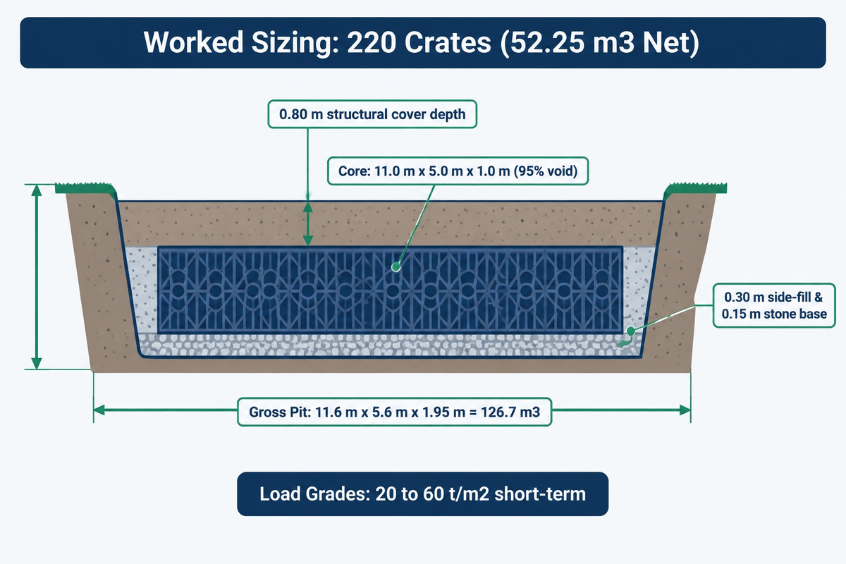
Short-term vertical crate compression test figures require long-term structural assessment for polymer creep and lateral earth loads under CIRIA C737, while gross pit excavation substantially exceeds net water volume: in our worked example below, 220 modules providing 52.25 m³ of net storage require a 126.7 m³ gross rectangular excavation (2.42 times net storage).
On Storm Manage’s published ST-series specification schedule, the modular geocellular specification matrix spans four nominal compressive grades (ST-E20 at 20 t/m² for landscaped green areas with ≥250 mm cover, ST-L30 at 30 t/m² for passenger car parks, ST-M40 at 40 t/m² for delivery and fire-access lanes, and ST-H60 at 60 t/m² for heavy goods vehicle yards) plus ST-Custom project builds across 400 mm (190 L net) and 500 mm (237.5 L net) module heights at a 95% internal void ratio. As Storm Manage discloses on its design and installation page, historical vertical test data referenced CIRIA C680, whereas CIRIA C737 structural design guidance for modular geocellular tanks (which superseded C680 in April 2016) requires project-specific creep reduction factors, lateral soil-pressure checks, and cover-depth verification.
Estimators misprice earthworks when they divide net storage by 0.95 and budget muck-away based on the bare crate volume. Although 95%-void modules hold approximately 2.4 times more water (by volume) than the 40%-porosity crushed stone aggregate cited in Philadelphia Water Department Chapter 4, every buried crate array is within a stone bedding, a backfill, and a cover envelope. Site drainage must ensure that unscreened sediment from a roadside ditch isn’t within the stone surround.
Worked Example: Sizing a 50.0 m³ Net Underground Tank vs Gross Pit Excavation
Assumed design inputs: Hydraulic modeling requires 50.0 m³ of net underground storage, and, using published data, Storm Manage ST-series 500 mm crates (1.0 m × 0.5 m × 0.5 m = 0.25 m³ gross volume and 0.2375 m³ net storage at 95% void ratio), two layers high (1.0 m) with a 150 mm base and 300 mm side-fill on each side, and an 800 mm finished, trafficked cover in a vertical-sided trench shoring, provide a complete system.
Dividing 50.0 m³ by 0.2375 m³ per module yields 210.53 modules, so a 50 m³ net storage array would need at least 211 Storm Manage ST-series 500 mm units (= 52.75 m³ crate volume, holding 50.11 m³ net water).
Rounding to a full rectangular two-layer grid of 11 units long (11.0 m) by 10 units wide (5.0 m) by 2 layers high (1.0 m) yields 220 modules, a 55.0 m³ gross crate block, and 52.25 m³ of installed net storage.
Adding a 0.30 m backfill on each side and 0.15 m base and 0.80 m cover creates an 11.6 m × 5.6 m × 1.95 m trench of 126.7 m³ gross excavation, which is approximately 2.42 times the 52.25 m³ net storage.
A smaller 200-crate reference block, measuring 10.0 m × 5.0 m × 1.0 m (47.5 m³ net water), would require the same 10.6 m × 5.6 m × 1.95 m bedding and cover envelope to fill the pit, and, therefore, 115.8 m³ of excavation.
Storing 52.25 m³ of treated stormwater within the 40%-porosity open-graded stone trench described in the Philadelphia Water Department Chapter 4 would require 130.6 m³ of washed stone, plus a cover depth, without the use of crates.
Installed Cost Breakdown: Modular Geocellular Crates vs Precast Concrete Vaults
The cost of installed underground storage varies based on the project structural load rating, conditions of groundwater uplift, seam testing of geosynthetics, and local earthwork rates; therefore, quotes should be evaluated on a per cubic meter basis of net water storage. Converting a porous soakaway to a sealed attenuation, detention, or OSD tank adds four specific scope items to the contract.
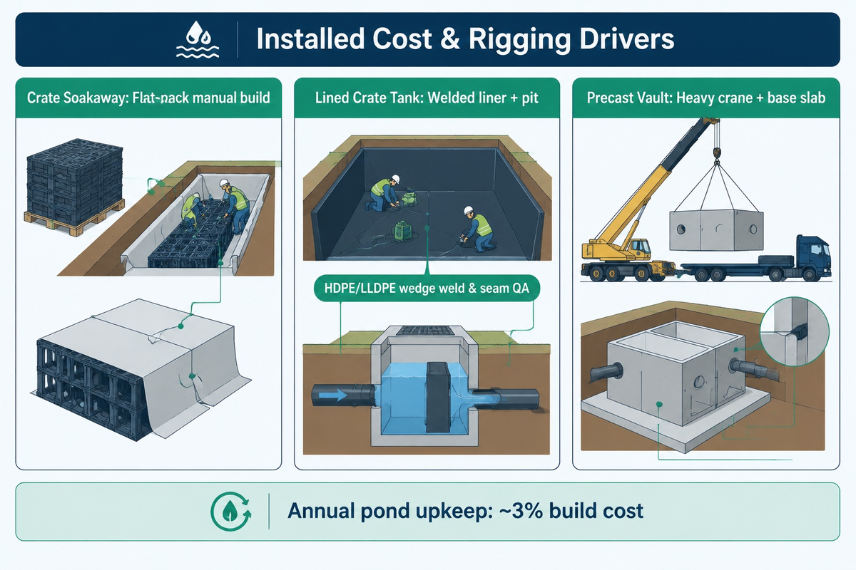
On a highly developed urban site, underground storage preserves the greatest share of developable land, keeping buildable area open for the greatest number of uses. While urban land acquisition often determines the economics of a surface water basin in urbanized areas, the cost section of the US EPA Wet Detention Ponds BMP Fact Sheet (citing King and Hagan, 2011) estimates routine annual pond maintenance at about 3% of construction cost. Underground storage tanks often become more economical than surface storage when land costs exceed the cost of trenching and storage installation.
Compared with rigging huge precast concrete vaults that require mobilizing multiple oversize haulage trucks and heavy mobile cranes, flat-packed polypropylene crates ship nested on standard trailers and assemble manually inside the shored excavation, while holding more water per unit pit volume than open-bottom arch chambers that rely heavily on the 40%-porosity washed stone surround cited in Philadelphia Water Department Chapter 4. Civil estimators evaluating options are invited to review our underground stormwater detention tank material comparison and seek a project-specific bill of quantities.
Civil Contractors, Commercial Property Managers and Residential Homeowner Associations pricing sealed Attenuation, detention or OSD Vaults against Permeable Crate Soakaways should break down their tender into the following four independent cost and scope categories:
Total Installed Cost Drivers & Four Soakaway-to-Sealed Scope Deltas
Cost / Scope Driver
Geotextile Crate Soakaway
Lined Crate Attenuation / Detention / OSD
Precast Concrete Detention Vault
Freight, Rigging & Quote Basis
Flat-packed pallet delivery, manual assembly; quote by net m³ storage and traffic grade
Flat-packed crate delivery plus specialist liner crew; quote by net m³ plus membrane and control pit
Multi-load heavy haulage plus mobile crane rigging and engineered concrete base slab
1. Geosynthetic Wrap & Seam Joining
Permeable non-woven geotextile overlapped around crate block
Impermeable geomembrane between protective fleeces + HDPE/LLDPE wedge welding (or EPDM seam tape) and QA testing
Butyl joint seals or external waterproofing membrane across panel joints
2. Pipe Penetrations & Air Venting
Collared inlet adaptor through permeable geotextile wrap
Sealed flanged pipe boots on inlet, base outlet, and high-level air-relief vent
Elastomeric seals fitted into formed or core-drilled concrete openings, or cast-in connectors
3. Downstream Flow-Control Chamber
None for standalone soakaway without a base outlet (exceedance overflow where specified)
Separate civil manhole or OSD Discharge Control Pit with vortex regulator or orifice plate + trash screen
Internal concrete baffle wall or external flow-control chamber
4. High-Groundwater Uplift Restraint
Not applicable (base sits above required seasonal high groundwater clearance)
Anti-flotation concrete slab, anchor straps, or overburden ballast where groundwater reaches tank level
Concrete self-weight aids uplift resistance; buoyancy is checked with the vault empty at design high water
Pretreatment, Silt Traps, CCTV Inspection Channels, and Maintenance Access
Subsurface soakaway and attenuation crates rely on upstream sediment traps and continuous internal inspection channels checked on a scheduled maintenance plan to prevent fine silt from blinding geotextile pores or stealing storage volume, whereas open surface ponds trade underground pipe jetting for turf mowing and standing-water mosquito management.
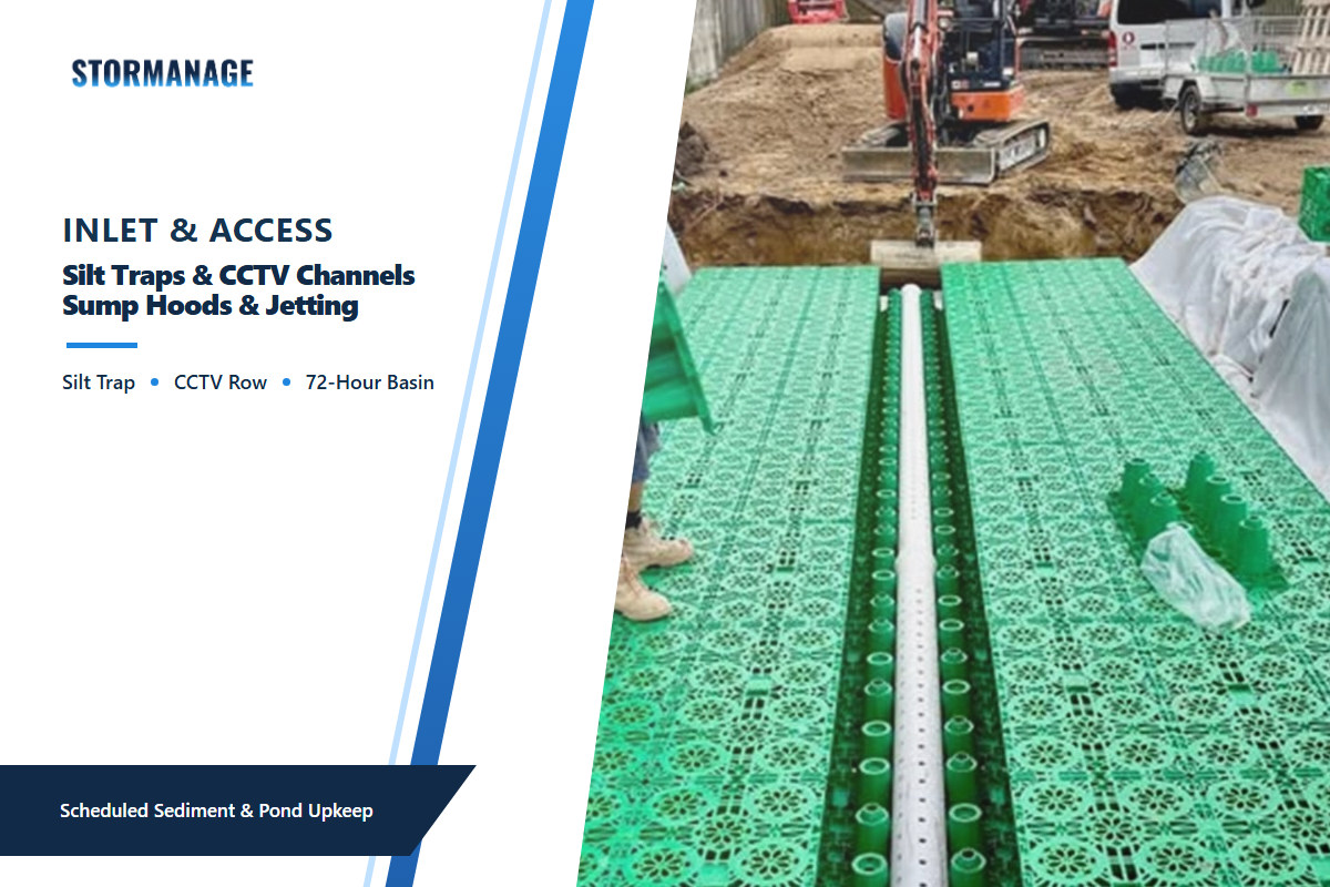
Untreated sediment from construction haul roads or asphalt parking bays rapidly degrades buried crates. Philadelphia Water Department Chapter 4 requirements mandate upstream pretreatment (such as sumps with trapping hoods, downstream trench-drain structures, or vegetated filter strips) on every subsurface detention inlet. Washed fines can clog the porous soakaway fabric and accumulate inside lined chambers. Within the module array itself, specifiers should verify unobstructed camera access: whereas precast concrete leg assemblies such as US Patent US6991402B2 for modular underground stormwater retention and detention assemblies form wide open internal channels, polypropylene crate arrays require aligned longitudinal and lateral inspection channels along the base row so wheeled CCTV inspection cameras and high-pressure water-jetting nozzles can flush settled sediment back toward an accessible catchpit sump.
What is a detention pond?
A dry detention basin (or a dry detention pond) is a surface vegetated excavated depression that temporarily stores stormwater runoff from roads and roofs and dries up within a municipal drawdown window (usually 72 hours as per Rutgers Cooperative Extension) through a low level outlet. A wet retention pond or lake is a water body that retains a permanent pool of water.
Choose buried crates where preserved parking or building land value outweighs underground excavation, installation, and surface reinstatement costs, and choose open basins where ample green space favors lower-cost surface earthworks. According to Rutgers Cooperative Extension Fact Sheet FS1195 (2012) on dry detention basins, conventional turf-lined basins typically drain within 72 hours in line with the 72-hour mosquito-control design limit cited from Metzger (2004), and FS1195 screens basins with outlet orifices larger than 3 inches (76 mm) as candidates for low-clogging naturalized conversion. Rutgers reports that converting weekly or biweekly turf mowing to naturalized wet-meadow vegetation cut once after autumn frost lowers annual vegetation management labor and fuel costs (varying by basin acreage and local mowing frequency), whereas permanent wet retention lakes often add an aerating fountain to support dissolved oxygen, wildlife habitat, and a healthy aquatic ecosystem. Beneath commercial paving, modular crates preserve surface parking above the tank (while retaining manhole access covers) and avoid open-water fencing.
Manufacturer Shortlist Criteria and Multi-Package RFQ Boundary Checklist
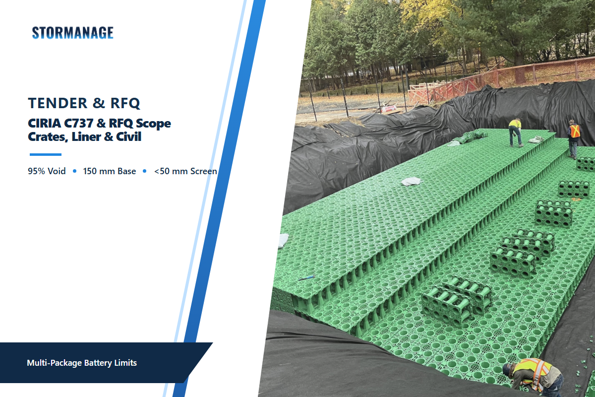
Engineers and buyers shortlisting geocellular crate manufacturers should verify CIRIA C737 long-term creep and lateral resistance calculations (noting CSA B184 Series:22 covers arch chambers rather than box crates) alongside continuous CCTV channel access, while splitting RFQ packages across crates, liner installation, flow controls, and civil earthworks.
Established commercial polypropylene crate references in international drainage specifications include Polypipe Polystorm, Wavin AquaCell and Q-Bic Plus, ACO StormBrixx, and GRAF EcoBloc, while Storm Manage publishes its ST-series polypropylene crate range in ST-E20, ST-L30, ST-M40, ST-H60, and ST-Custom grades at a 95% internal void ratio. Rather than comparing unfactored short-term crush numbers alone, engineers verify crate structural design life under CIRIA C737 (noting that CSA B184 Series:22 polymeric subsurface stormwater management structure standards currently cover arch-shaped chambers rather than crates), while sizing storage volume for local climate-change rainfall allowances and peak discharge rules in England’s 2025 National SuDS Standards or Australian council OSD codes.
When buying companies believe that one purchase order covers the entire project scope including membrane welding and trenching, disputes are common. Copy the six-row scope checklist below into commercial RFQ packages to lock battery limits across suppliers and civil contractors:
RFQ checklist: copy these into your quote request:
Nominal short-term crush figures do not establish sustained HGV traffic or lateral earth capacity
Request CIRIA C737 creep data and direction-specific lateral and vertical structural calculations for crate modules
Internal void ratio & crate geometry
95% published Storm Manage ST-series void ratio (190 L net per 400 mm unit; 237.5 L net per 500 mm unit)
Sets integer grid dimensions and separates net water storage from gross bedding-and-cover excavation
Check dimensional drawing and confirm 150 mm stone base plus 300 mm side-fill envelope
Geosynthetic wrap & seam method
Permeable non-woven geotextile (soakaway) or ≤10⁻⁸ m/s geomembrane between protective fleeces (sealed)
Angular aggregate can damage unprotected liners, and unsealed overlaps leak throttled storage
Confirm roll boundary; require dual-track wedge-weld air-channel logs on HDPE/LLDPE or seam-tape QA on EPDM
Air-relief vent & pipe penetrations
Sealed flanged pipe boots + top air vent on lined tanks; collared porous entry on soakaways
Unvented watertight envelopes trap air pockets during heavy inflow and restrict inlet capacity
For sealed tanks, verify flanged boots, vent sizing, and watertight seam tests; for soakaways, check collared geotextile wraps
Pretreatment & outlet control boundary
Upstream pretreatment sump/trap; blockage protection on <50 mm orifices (Defra) or >76 mm naturalization screen (Rutgers)
Crate suppliers furnish PP modules, while vortex regulators and DCP orifice plates sit in civil chambers
Assign upstream silt trap, downstream control chamber, and trash screen explicitly to civil scope
CCTV access & groundwater design
Continuous inspection channels; local wet-season groundwater clearance (infiltration) or uplift check (sealed)
Ballast resists flotation on sealed tanks exposed to groundwater but cannot replace infiltration soil separation
Review camera-row layout drawing, wet-season water-table logs, and signed empty-tank flotation calculations
Frequently Asked Questions
Q: How does a soakaway crate work?
A polypropylene crate soakaway receives, via an upstream silt trap, pre-screened roof or paved runoff, and is made of a matrix wrapped in geotextile.
Storm Manage’s published ST-series crates provide a 95% internal void ratio, allowing captured water to infiltrate into clean surrounding subsoil so soakaways draining over 100 m² empty half their volume within 24 hours under Shropshire Council’s BRE Digest 365 guidance.
Q: How deep should a detention pond be?
Dry surface detention basins usually hold shallow active storm water storage sized to local design-storm volume, and have an emergency spillway above the peak storage level.
Municipal design guides regulate vegetated side slopes for safe access for maintenance and size the low-level outlet structures to allow the basin floor to drain dry during the local drawdown period, such as the 72-hour typical dry-basin window mentioned by Rutgers Cooperative Extension.
Q: Do detention ponds attract mosquitoes?
Rutgers Cooperative Extension advises that designing dry detention basins to drain in 72 hours cuts mosquito breeding risk.
Citing Metzger (2004), Rutgers notes this 72 hour standing water design limit to control mosquito larvae, though even when a basin is graded to drain, poorly graded floor puddles, a clogged outlet, or unmaintained sumps can still create mosquito breeding habitat.
Q: Should detention ponds be mowed?
Conventional dry turf basins require weekly or bi-weekly mowing, while naturalized wet meadow basins require mowing once a year after autumn frost.
Scheduled cutting prevents woody roots from damaging embankments.
Q: Can the same geocellular crates be used for rainwater harvesting as well as detention?
Yes, identical structural polypropylene modules (such as 400 mm or 500 mm Storm Manage ST-series crates) form non-potable reuse cisterns when enclosed in a watertight geomembrane, though pipework changes completely.
Rather than draining dry through a base orifice, modular rainwater harvesting tank configurations seal the bottom of the tanks, add pre-tank debris filtration, and place a submersible pump in an extraction chamber for irrigation or washdown reuse, and provide a high level overflow for surcharge inflow.
Q: Why do councils require a minimum orifice diameter on OSD and attenuation outlets?
England’s 2025 SuDS Standards require blockage protection on orifices under 50 mm, while Rutgers FS1195 screens pond orifices above 76 mm as less prone to debris clogging during naturalization.
Trash screens and vortex regulators still require scheduled cleaning.
Q: Can an infiltration soakaway be combined with an overflow attenuation tank on marginal soils?
Yes, hybrid SuDS designs combine ground infiltration with throttled pipe discharge where soil permeability is unable to empty stormwater within the permitted drawdown time.
Hydraulic drawdown modeling takes into account measured field infiltration rates, effective infiltration surfaces, stored volume, and continuous inflow (rain event). Stormwater is permitted to infiltrate into subsoil above the seasonal groundwater level and surcharged water is diverted through a flow regulator to a surface water body.
Need Module Takeoffs for a Soakaway, Attenuation, Detention, or OSD Layout?
Our engineering team can prepare a module schedule across ST-E20 through ST-H60 and ST-Custom grades along with permeable geotextile or impermeable geomembrane quantities.
How Our Drainage Team Compiled This Cross-Regional Guide
Storm Manage manufactures interlocking polypropylene soakaway, attenuation, detention, and rainwater harvesting modules across nominal vertical grades ST-E20 through ST-H60 and ST-Custom. To help civil specifiers reconcile UK SuDS, US NPDES, and Australian council OSD drawings, our technical team cross-checked published Storm Manage ST-series 95%-void module dimensions and our worked sizing example (50.0 m³ required net storage, 52.25 m³ installed net capacity, and 126.7 m³ gross excavation) against England’s June 2025 Defra SuDS Standards, BRE Digest 365, CIRIA C737, and municipal stormwater manuals.