We use the details you submit to review and respond to your project enquiry. Entries are handled in this website’s WordPress database using Fluent Forms; our hosting and email providers may process the submitted details. Other technical providers receive only the data described in our Privacy Policy.
Please do not send passwords, payment-card details, government identification numbers, sensitive personal data, or unnecessary confidential third-party information.
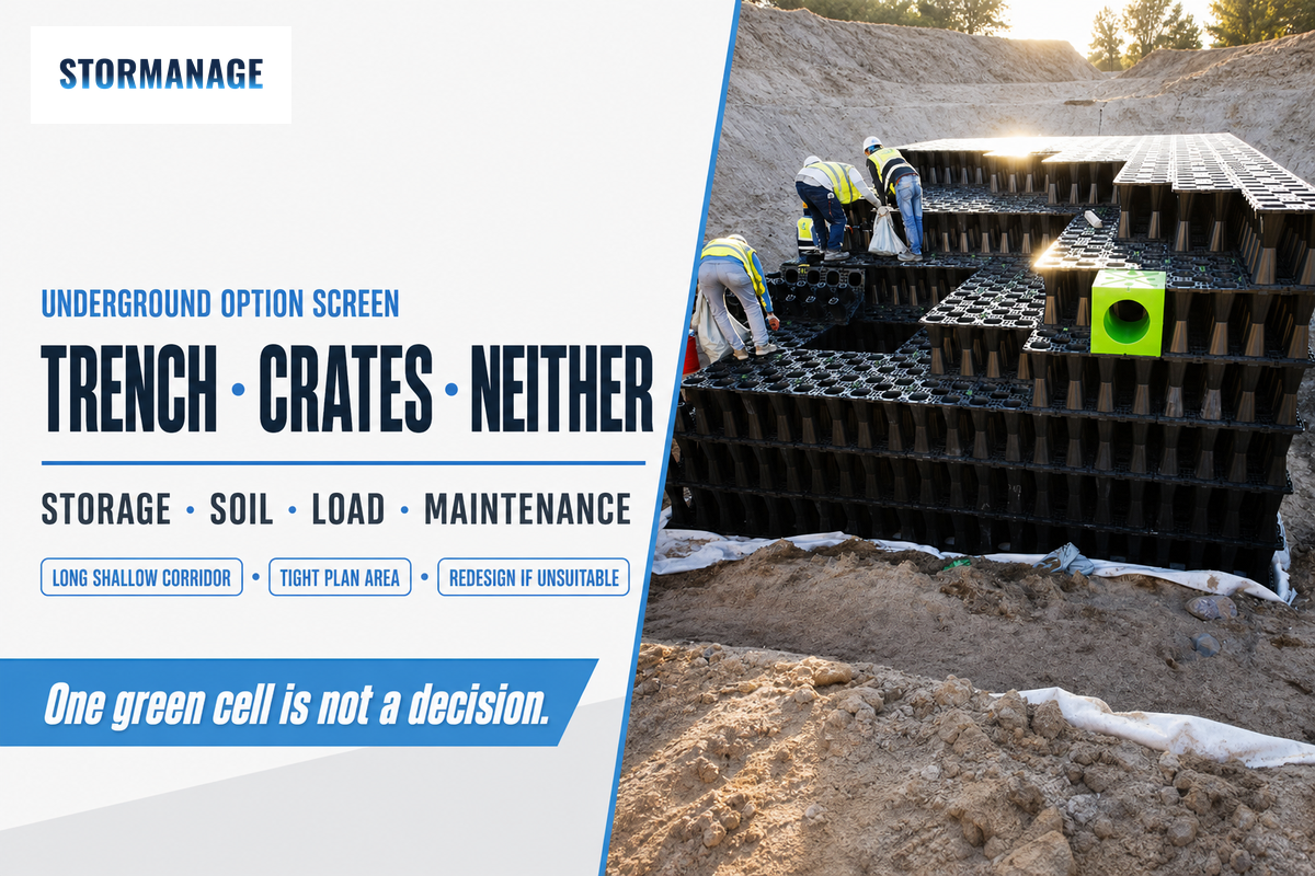
An infiltration trench and a geocellular soakaway can both provide runoff space, but solve different aspects of the drainage problem. The trench offers a long soil contact interface and some treatment with clean aggregate. Crates provide even more storage space in a smaller package. Neither option can rescue unsuitable soil, high groundwater, a weak pollution strategy or a layout with no practical maintenance route.
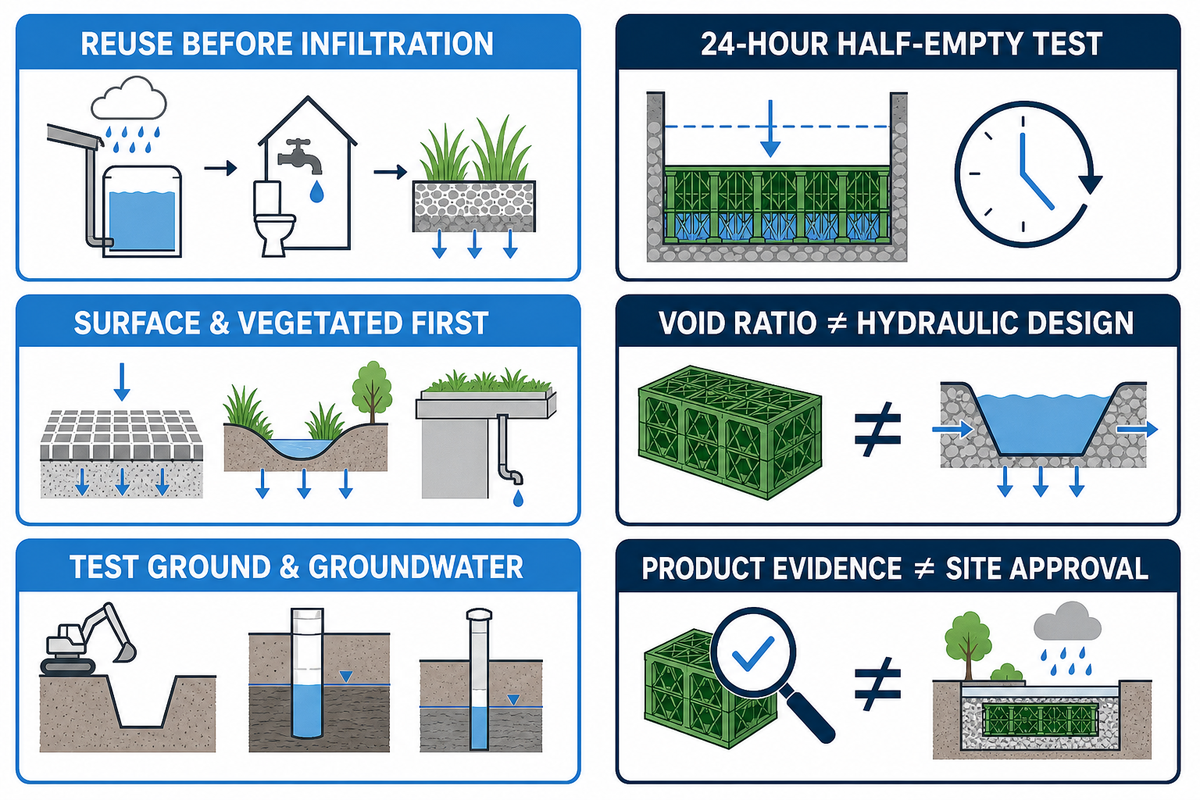
This guide compares the two as engineering concepts for UK projects. It begins one step before product selection: England’s 2025 SuDS hierarchy asks the project team to consider non-potable reuse, higher-priority discharge destinations and surface or vegetated features before narrowing the decision to an underground infiltration system.
A trench and infiltration basins are both described as BMPs in wider stormwater management guidance; those labels don’t mean the devices can be interchanged. The aim may be to reduce runoff and support groundwater recharge, but only where the site evidence supports that route. Seasonal high groundwater or an impermeable layer can stop percolation. A subsurface reservoir may provide storage and support groundwater recharge where the site evidence permits infiltration, but it cannot make unsuitable ground accept water.
The short answer
Use a stone-filled trench when a shallow linear corridor, broad soil contact and a visible pretreatment path matter more than compact storage. Develop a crate option when plan area is tight and the exact module, cover, loading and inspection arrangement can be evidenced. Choose neither when field testing, groundwater, pollution risk or the wider drainage hierarchy rules out infiltration.
What an Infiltration Trench Actually Stores, and Where the Water Goes
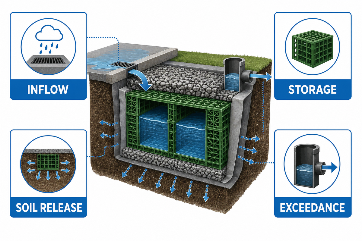
First, isolate the soil that must accept the water from the temporary storage medium. In the 2-Capacity Model, storage volume is separated from soil-release capacity.
What is an infiltration trench?
An infiltration trench is a shallow excavation filled with clean stone or another void-forming medium. Runoff enters the spaces between the particles, waits there temporarily, then moves through the base and sidewalls into suitable surrounding soil. A perforated distribution pipe may spread inflow along the trench, but the pipe doesn’t define the system’s capacity. The storage zone and the receiving ground do.
A conventional trench uses coarse gravel or washed stone as the storage medium. The top of the trench must be detailed so debris and pollutant-laden flow do not enter untreated. A filter strip can protect water quality before the inlet. The design of infiltration features must allow water to flow from the storage zone to soil, rather than just fill an excavation.
Release occurs across bottom and sides, not just through the pipe diameter. Any subsurface flow along the sides of the trench belongs in the drawdown model. Some sites may also develop lateral movement through adjacent strata. Where conditions are suitable, infiltration may replenish groundwater; that possible recharge benefit does not override pollution or ground constraints.
It’s easy to lose sight of that distinction when a drawing shows only a single box. Consider the system as the 2-Capacity Model instead.
2-Capacity Model: what fills, what empties and who owns the check
Upstream surcharge before the storage zone is full
Drainage designer
Storage capacity
Gross geometry multiplied by defensible effective void ratio
Available void fills before the design event is accommodated
Designer using product or aggregate data
Release capacity
Field infiltration evidence, wetted base and side area, groundwater
Water remains after the required drawdown period
Geotechnical and drainage team
Exceedance capacity
Overflow level, safe route and downstream consequence
Unplanned surface flooding or building ingress
Lead designer and approving body
Replacing rubble with a 95% void module can reduce the nominal storage zone, and leave the same drawdown problem unresolved.
Depth Is an Output: The Ground-Constraint Sequence
Depth is reflective of the hydraulic objective, field conditions and site constraints. It is not a product setting or a reusable rule of thumb.
How deep should an infiltration trench be?
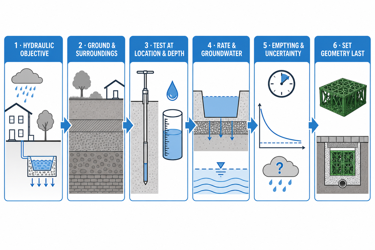
There is no responsible universal depth. The feasible invert emerges from investigation: proposed layout, representative field testing, maximum likely groundwater, restrictive layers, contamination, stability, the required drawdown and the authority’s acceptance basis. Copying a depth from another project reverses that sequence.
Clarify the hydraulic objective. Identify the catchment, critical event, climate adjustment, active storage, overflows and any permitted discharge.
Evaluate the ground and surrounding conditions. Review geology, contamination, potential slope, buildings, roads, utilities and the sensitivity of the receiving water.
Test at the proposed location and effective depth. A convenient shallow test elsewhere on the plot does not prove the intended interface.
Reconcile the rate with groundwater. A NERC-archived study states that higher groundwater can lower the empirical infiltration coefficient used in design; test season and maximum likely level shouldn’t be treated as unrelated inputs.
Check emptying and uncertainty. England’s 2025 standard requires the base to remain at least 1 m above maximum likely groundwater and the 3.3% annual-exceedance-probability runoff volume to half empty within 24 hours. It also requires safety factors for infiltration uncertainty.
Set invert and geometry last. Evidence should determine a workable invert and sufficient cover; if it does not, revise the strategy rather than forcing the trench or crate into a design drawing.
The same current standard says that point infiltration shouldn’t be relied on to discharge all runoff where the infiltration rate is less than 1×10⁻⁶ m/s. That is an England design condition, not an invitation to apply one laboratory number without a competent site assessment.
Changing the trench foundation or perimeter cannot compensate for a receiving layer that fails the investigation. The evidence should also distinguish filtration in a pretreatment component from infiltration into the ground; they are different functions.
The Project Input Register Before You Ask for a Crate Proposal
Starting the design process with a defined project envelope is useful. The table below defines what the buyer, designer, investigator, and supplier, respectively, must do before a module count is considered meaningful.
What information is needed to size an infiltration trench or geocellular soakaway?
A supplier can configure modules only after the project team defines the design problem. Sending a catchment area and requesting “the right number of crates” keeps the most important assumptions invisible. Use this 12-Field Project Input Register prior to requesting a proposal:
First, define what the connections are between gutter and drainage areas. Next, show how runoff is routed for the rainfall events. State the stormwater infiltration goal separately from storage volume. Overseas soil and water conservation or conservation district guidance may provide useful context, but it does not replace the applicable UK approval basis.
Input
What must be stated
1. Project location
Country, authority, site address and approval route
2. Catchment
Area, surface types, runoff coefficients and connected zones
3. Rainfall basis
Critical duration, return period, climate allowance and modelling source
4. Destination hierarchy
Water-reuse decision and why higher-priority destinations are or are not practicable
5. Storage objective
Required active volume, any controlled outlet and overflow route
6. Infiltration evidence
Method, locations, depths, repeats, results and adopted design value
7. Groundwater and strata
Maximum likely groundwater, monitoring season, bedrock and restrictive layers
8. Available envelope
Plan area, invert range, boundaries, utilities and adjacent infiltration features
9. Levels
Inlet, outlet, overflow, finished ground and cover constraints
10. Structural duty
Traffic class, wheel loads, construction loads and soil assumptions
11. Treatment and access
Pollution hazard, pretreatment, inspection and maintenance route
12. Deliverables
Calculation ownership, drawings, model evidence, accessories, packing and programme
The 4-Constraint Selection Matrix: Trench, Crates or Neither
The right trade-offs among the four constraints of storage capacity, ground interface, structural duty and maintainability should be made to determine the optimal underground route. The matrix shows the trade-offs and keeps “neither” available where infiltration isn’t justifiable.
When should I choose a stone-filled infiltration trench instead of geocellular soakaway crates?
First comes Gateway 0. Check that the wider drainage strategy has accounted for reuse, the runoff-destination hierarchy, source control, surface/vegetated features and multiple benefits. The matrix below is an underground-option screen after that; it isn’t a complete SuDS strategy.
“Higher cost alone shall not be a reason to utilise lower priority final destinations.”
England National Standards for Sustainable Drainage Systems, requirement 1.3
The four underground constraints are storage efficiency, effective infiltration interface, structural duty and maintainability. Use all four; a single green cell isn’t a decision.
A relatively small footprint may favour crates, while a treatment train still needs a filter strip upstream. Sediment traps need access so crews can remove accumulated sediment; burying that task behind an inaccessible inlet only postpones failure.
4-Constraint Selection Matrix
Project condition type
Route to develop
Why
Long, shallow verge with suitable soil
Trench
Linear geometry spreads soil contact and fits a narrow strip.
Very tight plan area, adequate depth and proven load design
Crates
High void ratio concentrates storage.
Slow tested soil with no viable controlled outlet
Neither
Extra void does not create release capacity.
Groundwater leaves less than the required separation
Neither / redesign
The feasible invert fails before media choice.
Sediment-prone runoff with accessible surface treatment
Trench or treatment train
A maintainable pretreatment path matters more than compact void.
Under trafficked paving
Crates, subject to design
Exact-model long-term strength, cover and saturated-soil checks are required.
Inspection route cannot reach a buried tank
Trench or redesign
Susdrain notes hidden geocellular systems can be difficult to monitor and maintain.
Contaminated land or unacceptable groundwater risk
Neither infiltration option
Use an appropriately contained strategy with competent approval.
Several soakaways close enough to interact
Needs designer
Groundwater mounding and capacity interaction can erase a single-unit footprint advantage.
Phased works with a long corridor and simple access
Trench
Segments can align with staged construction and local maintenance access.
If the matrix indicates modular storage, review the available modular soakaway crates only after the project inputs and evidence owner are clear.
The Void-to-Footprint Check: What the 30–40% vs 95–96% Comparison Proves
The limits of the arithmetic should always remain evident. For option screening:
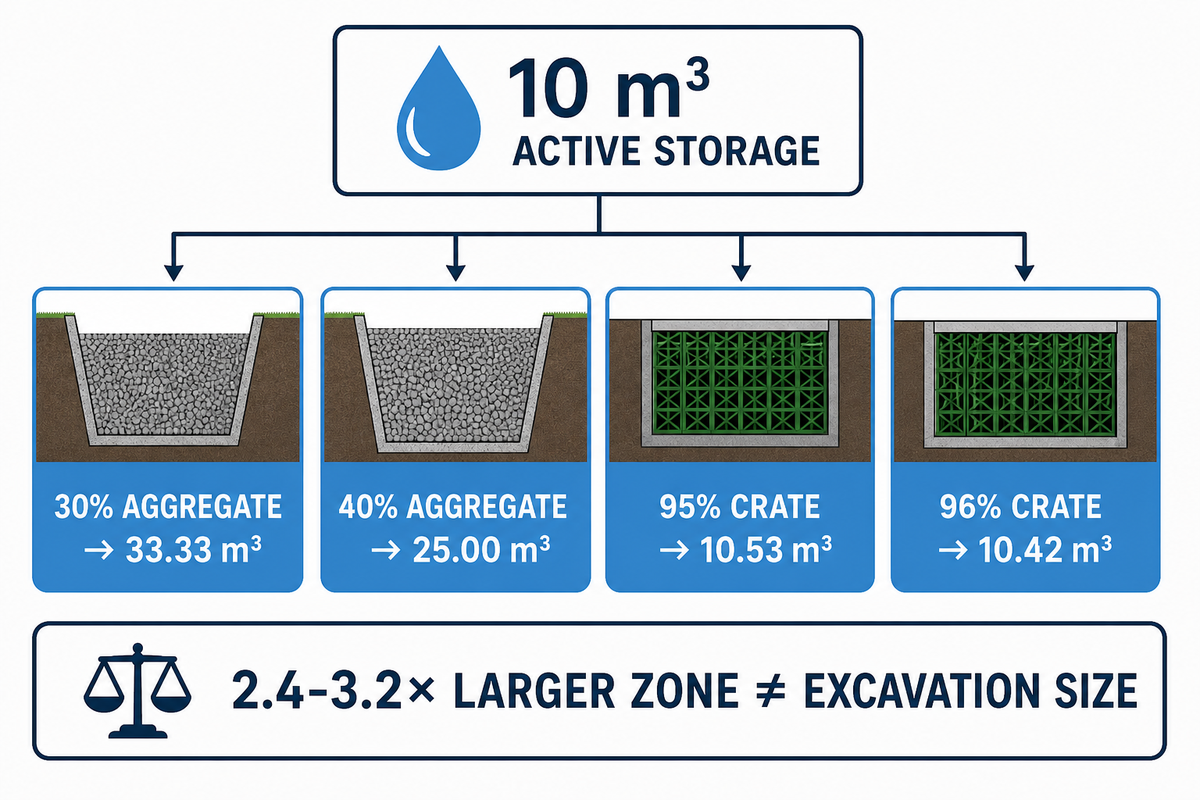
Gross storage-zone volume = required active storage ÷ assumed effective void ratio
Take a 10 m³ active-storage requirement. The 30% and 40% aggregate cases below are explicit sensitivity assumptions, not current universal constants. The crate cases come from exact BBA-certified configurations: Wavin AquaCell NG at 95%, and the GRAF EcoBloc base unit without its bottom plate at 96%.
The Wavin document is Product Sheet 7, Issue 1, dated 4 July 2023, and the GRAF document is Product Sheet 4, Issue 2, dated 18 December 2024. Treat both as versioned evidence for the named configurations and request the current certificate and product declaration prior to procurement.
Screening case
Void assumption
Gross zone for 10 m³
Relative to 95% crate
Clean aggregate sensitivity A
30%
33.33 m³
3.17×
Clean aggregate sensitivity B
40%
25.00 m³
2.38×
Wavin AquaCell NG certificate example
95%
10.53 m³
1.00×
GRAF base unit without bottom plate
96%
10.42 m³
0.99×
So, the illustrative aggregate storage zone is approximately 2.4 – 3.2 times larger. It does not prove a 2.4–3.2 times smaller excavation, cheaper installed system or equivalent infiltration performance.
What the calculation excludes
bedding, surround, cover, working space and side clearances;
shape limits, inlets, vents, inspection and pretreatment;
long-term loading, creep, saturated-soil behaviour and buoyancy;
the wetted soil area needed to achieve drawdown;
groundwater mounding and interaction between nearby facilities; and
the difference between a 95% complete unit and a 96% component configuration.
A public CD 530 page is often surfaced for a 20–40% fill-porosity range, but that page is now visibly marked superseded. That’s precisely why the table labels 30% and 40% as scenarios. Test the actual aggregate or use a defensible project value rather than turning an archived range into a current rule.
Detail, Pretreatment and Failure Control
Most failures occur through ordinary details: dirty construction runoff, smeared soil, a disconnected inspection route, or a geotextile note that does not say what it separates. The table provides observable symptoms, and suggests the next engineering check.
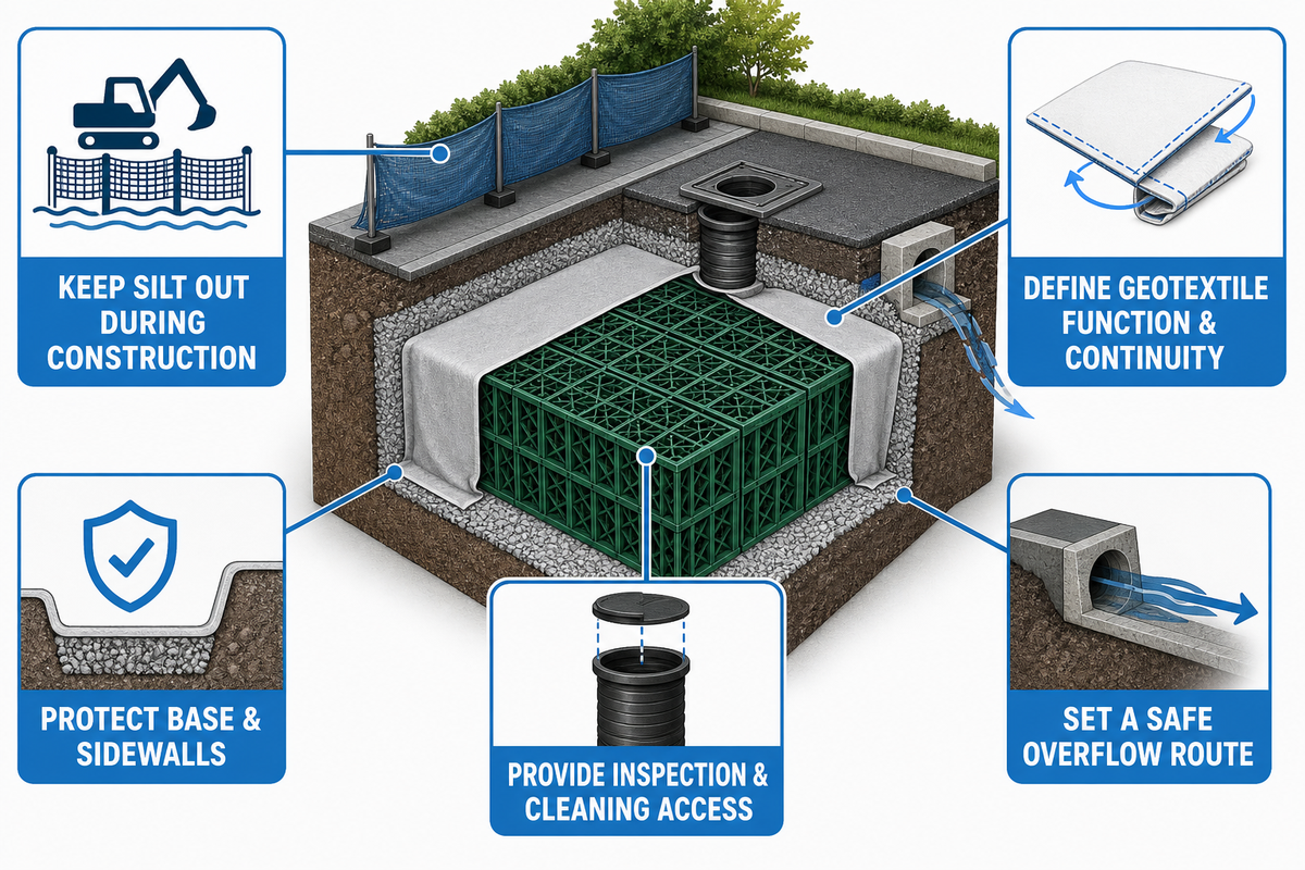
It’s reasonable to expect not all of the crushed stone supplies are clean. Finer particles can wash into the storage voids. A geotextile fabric works as a filter or separator only when its project-specific function and continuity are defined. Dirty inflow can clog the interface even if the nominal void volume is unchanged.
During construction, divert silt-laden surface water and control erosion before connecting the system. Conservation of the prepared infiltration interface is easier than attempting to restore it after trafficking or sediment entry.
Signal
Likely mechanism
Control or evidence
Water remains after the design drawdown
Soil rate, groundwater or clogging
Observation access; compare field evidence with actual level and inflow
Rapid loss of performance after handover
Construction silt entered the system
Keep the infiltration area offline until the catchment is stabilised
Silt beyond a basic trap
High-flow washout
Size and maintain pretreatment; consider a non-re-entraining separator where justified
Local ponding along a trench
Uneven distribution or level error
Check pipe slots, invert, stone grading and inlet arrangement
Reduced rate after excavation
Smearing or compaction of the interface
Protect and prepare base/sidewalls under the designer’s method
Fines migrate into stone or crates
Wrong or incomplete separation detail
Project-specific geotextile design and continuous installation checks
Crate distortion
Load, cover, orientation or backfill mismatch
Exact-model long-term structural check and approved construction sequence
Air locks or erratic filling
No effective vent route
Show vents and high points on the configuration drawing
Overflow reaches a building
Undefined exceedance path
Set overflow level and safe surface route before construction
No one can inspect or clean it
Maintenance designed after the layout
Define access, isolation and maintenance triggers at concept stage
Crate bedding, wraps and connections should be defined on the issued-for-construction drawings and not improvised from a product photo. See these soakaway crate installation details for the installation topics that need project confirmation.
The Supplier Evidence Pack: What to Request and What It Proves
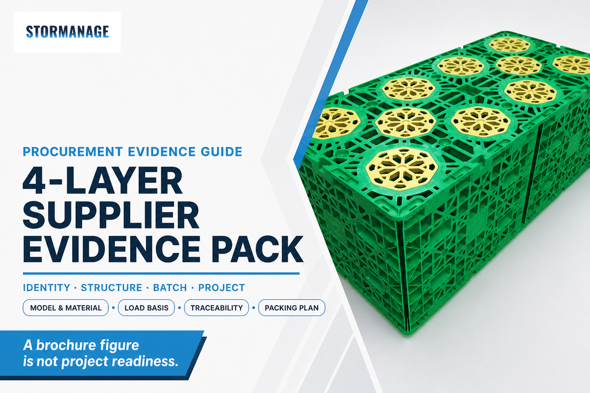
A brochure load figure doesn’t signify project readiness. Ask for four evidence layers and keep their purposes distinct.
4-Layer Supplier Evidence Pack
Layer
Request
What it can prove
What it cannot prove
1. Product identity
Exact model, material, unit mass, dimensions, storage and accessories
What is being offered
Site suitability
2. Structural basis
Short- and long-term values, orientation, test basis, cover/loading assumptions
Inputs available for a project check
A completed structural design for unknown ground
3. Batch control
Material control, weight tolerance, dimensions, traceability and inspection records
Manufacturing consistency controls
Performance outside the verified configuration
4. Project package
Layout, connectors, end caps, quantities, packing list, loading plan and lead time
Whether the order is complete and buildable as supplied
Hydraulic approval or ground acceptance
Storm Manage reports that their supporting Shenzhen injection-molding facility spans 8,000 square meters, houses eight 1000T-2000T machines, and maintains 12+ mold sets for standard, heavy-duty, shallow, and accessory variants. Storm Manage states monthly output of about 5,000 m³ and annual capacity above 60,000 m³ for finished modular crate modules. Its stated batch controls cover compression checks, dimensional tolerance, Virgin PP/Recycled PP material-ratio control and unit-weight consistency.
For export planning, Storm Manage states a typical 15–30 day lead time after order confirmation and up to 330 m³ of installed storage volume in a 40HQ under optimised stacking. Those are supplier-provided operating figures, not third-party audited performance claims. Confirm the exact model, quantity, loading plan and current programme on the quotation.
The wider Storm Manage modular stormwater systems range covers soakaway, attenuation, detention and rainwater-harvesting applications; the selected configuration still has to follow the project’s hydraulic and structural design.
What Changed in UK SuDS, and What Did Not
Defra published England’s new National Standards for Sustainable Drainage Systems on 19 June 2025 and updated the page on 30 July 2025. The publication calls them non-statutory standards for England. They can support new development and retrofit, though the official page says not every part may apply directly to retrofit.
What changed
a clear hierarchy led by non-potable reuse, then infiltration;
stronger emphasis on surface, vegetated and multi-benefit features;
explicit ground investigation, infiltration testing and groundwater duties;
a 24-hour half-empty test for the 3.3% event;
visible sediment-control, maintenance and structural-integrity requirements.
What did not change
poor ground doesn’t become permeable because storage is modular;
groundwater and contamination still constrain the feasible invert;
void ratio isn’t a substitute for a hydraulic calculation;
product evidence isn’t a site or approval decision;
one underground option isn’t automatically the best SuDS approach.
Use the UK SuDS development guide to support your planning view, alongside the latest local authority standards for the project.
Frequently Asked Questions
What is the difference between an infiltration trench and a French drain?
An infiltration trench is designed to hold runoff in the voids of stone or another medium and release it through the base and sides. A French drain is a linear collection and conveyance detail around a perforated pipe, but some infiltration may occur. Look at the calculation, outlet, pipe purpose and maintenance route rather than relying on the label.
Can an infiltration trench work in clay soil?
Don’t make a decision about clay, for instance, based on a single test. Establish the maximum likely groundwater and check for restrictive or contaminated layers. A deeper permeable horizon may exist, or the site may fail the required drawdown. The trench geometry also matters because a long, shallow system exposes a different infiltration interface from a compact chamber. If the soil can’t accept the design volume within the time allowed, the constraint can’t be addressed with additional aggregate or higher-void crates. The project may need attenuation with a controlled outlet, a different location or another drainage strategy.
How much larger is an aggregate soakaway than a crate system?
In the worked screening example, 10 m³ of active storage needs 25.0–33.33 m³ of aggregate storage zone at separately assumed 40% and 30% effective voids. A named 95–96% geocellular configuration needs about 10.42–10.53 m³. The aggregate zone is therefore roughly 2.4–3.2 times larger. That’s a storage-media comparison, not a finished excavation comparison: cover, bedding, side clearances, loading, maintenance and infiltration interface still need project design.
Do geocellular crates improve infiltration?
Crates increase storage efficiency; they do not improve the tested soil infiltration rate. Release still depends on the receiving ground, groundwater, the interface and pretreatment, and the drawdown design.
What should I send a supplier before asking for a soakaway-crate proposal?
Start with the project location, catchment area and surface types, rainfall basis, required active storage and any permitted discharge. Include results from field infiltration tests, test locations and depths, maximum likely groundwater, restrictive layers, available footprint, proposed invert, inlet and overflow levels, traffic duty, cover limits, pretreatment and maintenance access. State the approval basis and who owns the hydraulic and structural design. Mark every input as confirmed, provisional or missing and include a drawing revision. The supplier can then return a precise module arrangement, accessories, technical evidence and packaging without silently making assumptions about site conditions. The civil designer and approving authority still make that assessment.
Move from option screen to a project-ready crate proposal
Provide project constraints, loading duty and required storage. Storm Manage can return a configuration, accessory list, technical drawing and a container-loading basis for your designer to assess.
The Storm Manage team supplied the company capability information used in this article. The comparison used the latest England government guidance, local authority material, public technical guidance and precise product BBA certificates. Supplier capability statements are identified as Storm Manage statements; archived, overseas and local-only criteria aren’t presented as universal UK rules.