We use the details you submit to review and respond to your project enquiry. Entries are handled in this website’s WordPress database using Fluent Forms; our hosting and email providers may process the submitted details. Other technical providers receive only the data described in our Privacy Policy.
Please do not send passwords, payment-card details, government identification numbers, sensitive personal data, or unnecessary confidential third-party information.
Underground stormwater storage systems are the buried tank or crate modules that hold back stormwater runoff a sports pitch, landscaped site or podium deck can’t release all at once.
Quick Reference: The Project-Stage Snapshot
Site assessment + drainage strategy
2-4 weeks
Consent / planning consultation
4-12 weeks, jurisdiction-dependent
Specification + supplier tender
2-3 weeks
Procurement + shipping
15-30 days ex-works, plus transit
Installation
Days to weeks, scaled to volume
Inspection, sign-off, handover
Ongoing, first review at 12 months
Managing stormwater runoff this way is a planning and consent question well before it’s a product question. Search-trend data puts demand for underground stormwater storage systems up an estimated 52% year on year, with many of those seeking them currently trying to determine what must happen in what order before they can ask a supplier for a quote.
TL;DR
The surface drainage of a sports pitch and the storage system below it are two different, distinct design disciplines and confusion between them is the single biggest cause of over-specification.
England’s runoff hierarchy of needs places infiltration in front of piped storage-and-release, so a sealed attenuation tank is a secondary consideration you reach when infiltration can’t be employed, not a primary alternative.
With podium decks, there’s the added need for two approvals a ground-level pitch never needs – a structural engineer to sign off on load capacity, and a waterproofing contractor for the deck construction.
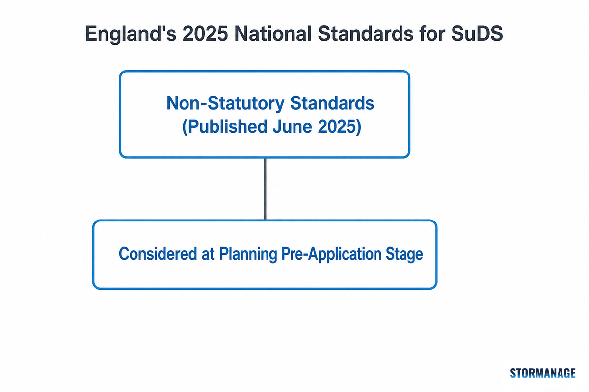
England’s new, non-statutory National Standards for SuDS were published in June 2025, and will be taken into consideration by planners assessing whether a development proposal meets the drainage hierarchy.
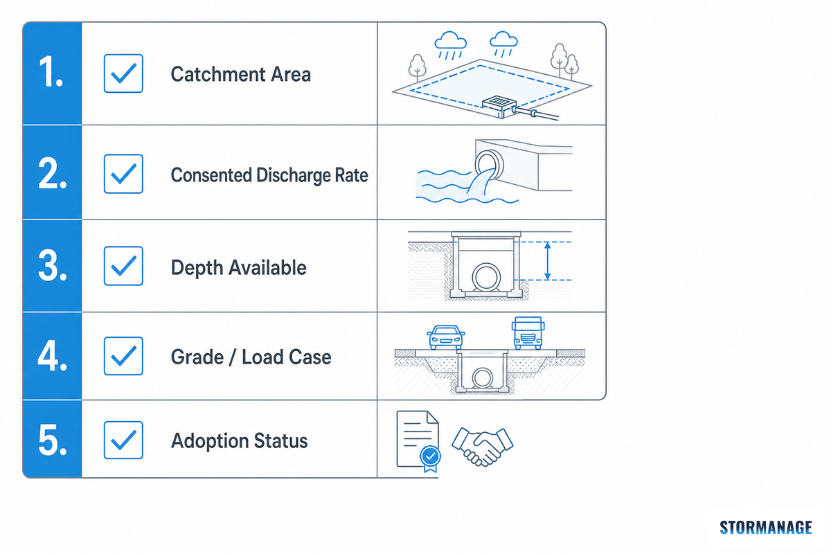
To get three competitive supplier quotes for your specification, you need just five key data points: area, consent, depth, load, and adoption.
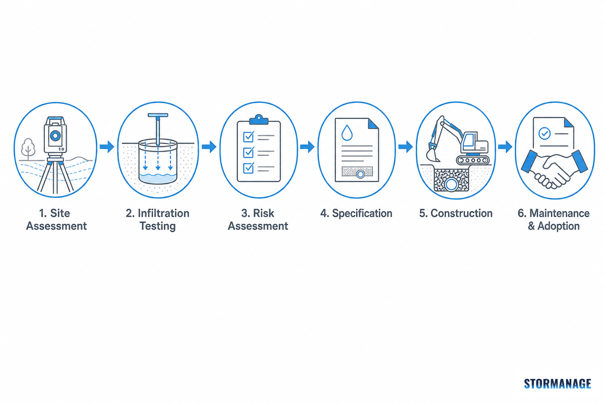
In short: a compliant scheme comprises six steps – site assessment, infiltration design and testing, risk assessment, specification, construction, and maintenance/handover – each with its own approving body relevant to your type of development. This guide take a buyer or specifier through that process specifically for sports pitches, landscape schemes, and podium decks, and leaves the crate-grade engineering detail to our sports, landscape & podium solutions page.
What “Underground Stormwater Storage” Actually Means for a Sports, Landscape or Podium Project
underground stormwater storage refers to any type of buried void – either crate module, pre-cast vault or arch chamber – which holds runoff temporarily and then releases it at a controlled rate, either as and when it has to or allowing it to seep into the ground. It’s a more restricted job than that may suggest and terminology for these underground stormwater systems and storage structures is applied loosely, meaning that buyers are quite frequently purchasing the wrong item.
What Are Underground Stormwater Detention Systems?
An underground stormwater detention system describes any type of buried system – crate module, stormwater detention vault, or chamber – that will intercept post-development runoff and discharge it at a controlled rate equivalent to the flow that would have left the site without the intervention, within limits of consent.
According to the CT Stormwater Quality Manual, underground detention structures are subsurface storage practices designed to temporarily detain runoff at a controlled, pre-development-equivalent rate, the same logic that governs a sports pitch or podium deck scheme, whether the catchment feeding it is a stadium roof, a landscaped car park, or the parking lots surrounding a podium development, regardless of jurisdiction.
That underground storage system can take on a different function according to how it’s clad – as a soakaway, sometimes described as an infiltration system, it’s geotextile-wrapped for infiltration into the surrounding ground, as a sealed attenuation tank it has a welded impermeable membrane and flow control – rather than as an underground retention system, occasionally labelled underground stormwater retention, which is built to store water and only discharges it during rainfall. That CT manual, in turn, classifies underground detention as one of several stormwater best management practices, alongside surface-level controls such as bioretention and vegetated swales – useful context if a reviewing engineer references BMPs generically rather than naming the crate system directly.
~52%
Est. YoY search growth, underground stormwater storage systems
6
Sign-off stages, site to handover
2025
England’s National Standards for SuDS published
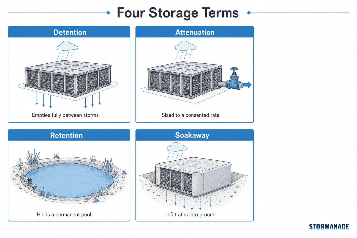
Detention, retention, attenuation and soakaway are not interchangeable — the wrap and outlet decide which one you have.
Term
What It Does
Typical Build
Detention
Holds runoff temporarily, empties fully between storms
Crate/vault + outlet flow control
Attenuation
Detention specifically sized to a consented discharge rate
Sealed membrane + orifice/vortex control
Retention
Holds a permanent pool, does not fully empty – the mechanism behind stormwater retention
Retention pond, or a lined below-ground basin equivalent
Soakaway crates
Infiltrates stored water into surrounding ground
Same crate, wrapped in permeable geotextile
Key takeaway: understand which of these four words describes your scheme before you call a supplier. It impacts on the wrap, the outlet hardware and the authority that’s concerned with your development.
The Six-Stage Sign-Off Map, From Site Assessment to Handover
The standard customer approaching a supplier is thinking of a quantity of units and a delivery date, then discovers mid-project that they should have handled consent paperwork, structural approval, or adoption documentation first. UK planning guidance provides clarity on what a surface-water drainage submission actually needs: existing drainage, existing rate and volume, the proposed scheme, a hierarchy justification, and a maintenance/adoption plan – all before construction starts. That’s a design and consent workload, not a procurement task, and it sits upstream of anything a supplier control.
The Six-Stage Sign-Off Map
Site & existing-drainage assessmentcatchment area, current runoff rate, soil and groundwater data.
Scheme design + infiltration assessmentinfiltration testing determines whether a soakaway or sealed tank gets installed.
Risk assessmentflooding, health and safety, and structural load (in the case of podium deck schemes).
Specification against a storage checklistgrade, volume, access, connections, and method of adoption.
Construction assessmentverifies the installation process complies with the approved design.
Maintenance inspection + adoption handoverthe document trail signed off by the authority responsible for approving the scheme.
This series of actions correlates to the CIRIA SuDS Manual (C753) checklist used to assess scheme design, infiltration, construction, and adoption transfer, it’s not a sales checklist, but the actual procedure used for assessing these schemes. The structure of the process stays generally consistent, but the authorities signing off at each stage vary by development type: a residential scheme heading for water-company adoption follows a different documentation stack than a private commercial podium deck retained by its own managing agent. Think of this as the shape of the process, not a fixed list of parties you need to convince.
“A load-out schedule tells you nothing if the consent hasn’t cleared yet. We’ve seen buyers spec a system, get a quote, place the order, and then find out the local flood authority wants a different discharge rate than the one the design assumed. Get the consent stage confirmed before you lock a spec.”
Buyers ask suppliers for a spec sheet first and a sign-off route second, most schemes fail in the opposite order.
Storage or Infiltration? The Buyer-Side Version of the Wrap Decision
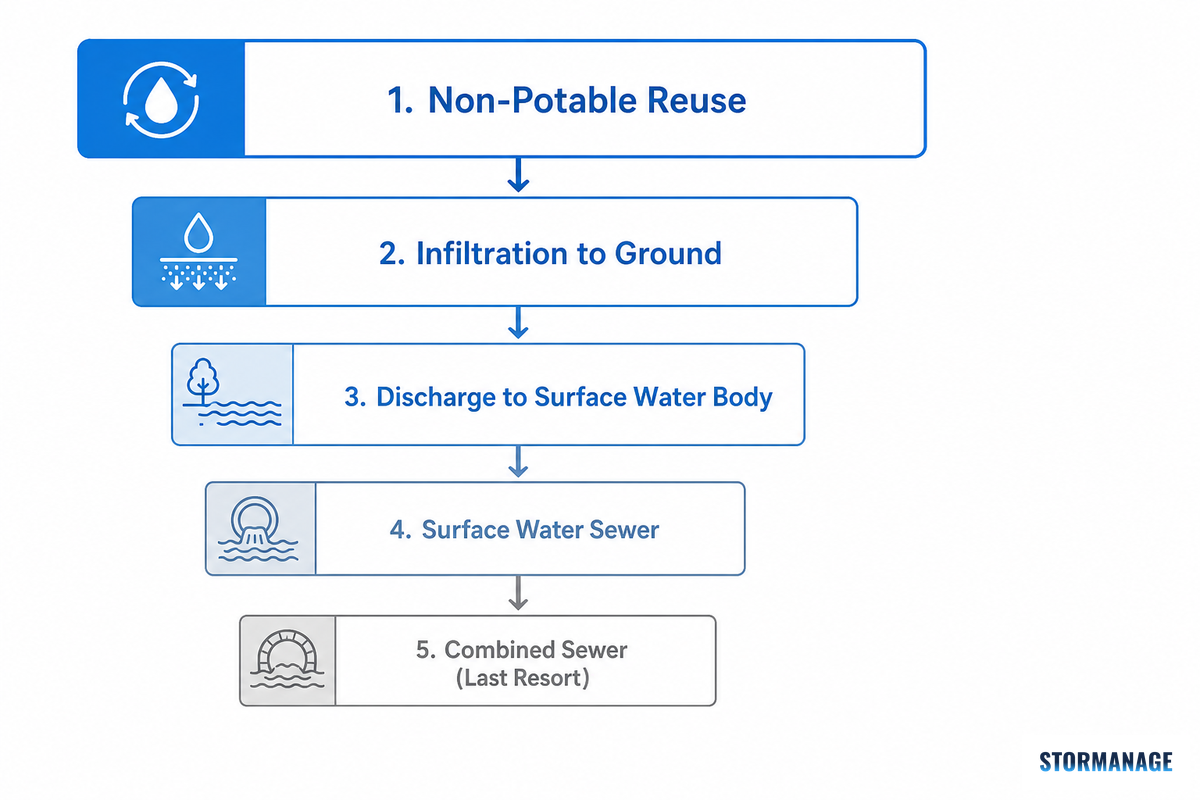
England’s national drainage guidance sets out a destination hierarchy, which is tighter than most clients realize: non-potable reuse first, infiltration to ground second, discharge to a surface water body third, a surface water sewer fourth, and a combined sewer last – the same hierarchy that governs how public sewer systems accept new connections – and, crucially, the standards specify that increased cost alone is not sufficient grounds to opt for a lower-ranking destination. In practical terms, that means a sealed attenuation tank isn’t an alternative option to a soakaway; it’s what you specify once infiltration has been evaluated and discounted.
Before you ask a supplier for a soakaway vs. attenuation quote, check:
Has a percolation test proved (or disproved) infiltration-compatible ground?
Is the site on clay, contaminated ground, or does it have a documented high water table?
Is the base of the proposed system clear of the maximum likely groundwater level?
If infiltration is possible, can you justify not pursuing it purely on cost grounds? (Under the hierarchy, you can’t.)
If infiltration is ruled out, that triggers a sealed, welded-membrane attenuation construction with a controlled outfall – the engineering detail for the grade selection and sizing is found on our sports field drainage storage crates page, so we don’t reproduce the derating tables here. What we should highlight is that some academic modelling has shown that distributed green infrastructure (such as bioretention cells or sunken green space) can out-perform tank storage on both water-quality and biodiversity grounds. This comparison is fair in open landscape contexts, but not for a playing surface which needs to remain flat and useable; there’s simply no room for a bioretention basin in the centre of a football pitch.
Sports Pitches and Golf Courses: Where Storage Fits Around the Collection Layer
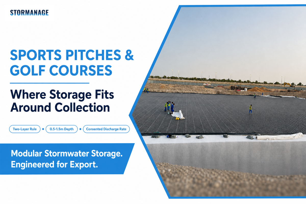
The biggest over-specification error in a sports scheme is to treat the pitch’s surface drainage and its underlying storage as a single system devised by one individual. They’re two different systems: our solutions page call this the two-layer rule. The first layer – the collection layer – removes water from a playable surface quickly enough to keep it in use, and this is an agronomist/ drainage contractor’s design; the second – buried at 0.5-1.5m deep – holds the water storage volume delivered by the first layer and releases it at an agreed rate, and it’s this underground detention system which our products are engineered for.
⚠️Common Mistake
Sizing underground storage capacity off the collection layer’s pipe network instead of the site’s consented discharge rate and its actual peak stormwater flows. Those two numbers are unrelated, a bigger pipe network moves water faster off the surface, it does not change how much your local authority will let you discharge downstream. Specifying off pipe capacity rather than the consent is how projects end up with tanks two or three sizes larger than they need.
One civil engineer’s field question on a forum captures the stakes directly: a scheme paired a sports surface with underground parking below it, and the design team didn’t want storage placed directly under the building – they needed to know whether anyone had successfully incorporated stormwater storage into an adjacent structure instead. This kind of coordination question is exactly what a Six-Stage sign-off catches at the earliest stage. Whose call is it whether storage goes under the pitch, under an access road, or under a car park?
💡Pro Tip
Industry briefing work on sustainable drainage for sports pitch developments has questioned whether existing sports field drainage design sometimes carries more attenuation capacity than the pitch’s actual measured runoff requires, an apparent over-design pattern common to golf course drainage systems as much as football pitches, not a universal rule. Base sizing on your site’s actual consented discharge rate and catchment data, not a rule-of-thumb multiplier carried over from a different pitch type.
NAAC’s Guidelines for Sportsturf Drainage Installation similarly describe drainage as site-specific stormwater design, not a spec – the very same planning that helps to manage storage volume and avoid over-specification.
Podium Decks and Landscape Over Structure: The Extra Sign-Offs You Need
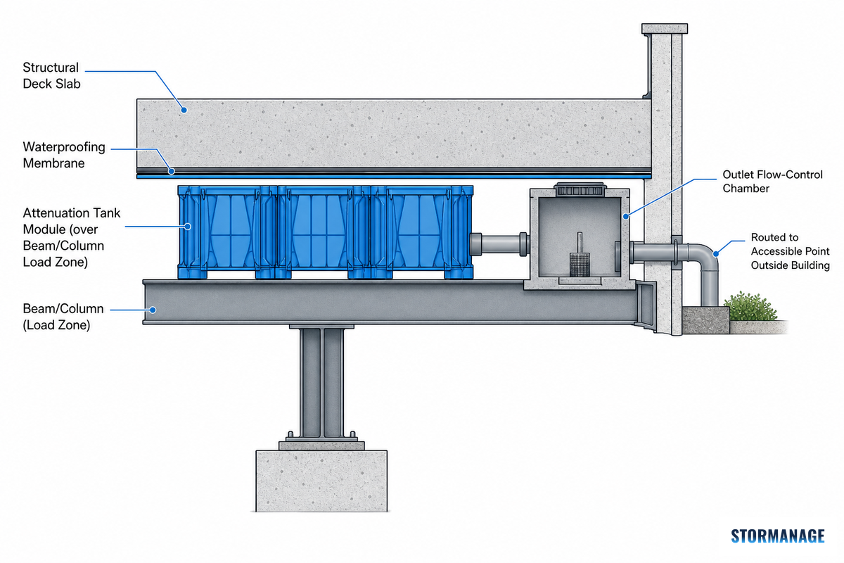
Podium schemes exist in the first place because land availability at grade is limited and paved areas leave little room for surface attenuation, which is why the storage moves onto or into the structure instead and introduces a couple more disciplines to the sign-off list that an at-grade sports pitch or park doesn’t need. Firstly, a structural engineer has to verify that the deck structure is capable of supporting the dead and saturated loads from a bulk attenuation system (load case, not drainage). Secondly, podium deck waterproofing needs sign-off from a specialist contractor to confirm the build-up complements rather than contradicts the system; a bulk attenuation crate isn’t a substitute for a purpose-built deck drainage layer, and vice versa.
💡Pro Tip
Philadelphia Water Department guidance caps a vegetated deck drainage layer at under 150mm total, with a minimum 100mm growing medium, well short of the 400-500mm module height a bulk storage crate needs. That’s exactly why bulk attenuation belongs in a dedicated tank zone or deep planting pit, not folded into the thin deck drainage layer itself; exact depth limits vary by manual and jurisdiction, so confirm against the specific design manual your project falls under.
Where Should an Attenuation Tank Be Located on a Podium Deck?
When you’ve a podium deck, placement will primarily be driven by structural load points before hydraulics; you’ll want the tank positioned in an area proven by the structure engineer to support the saturated load of the stored water, often directly over beams or columns.
Before finalizing the waterproofing detail, confirm:
Tank location sits within the structural engineer’s confirmed load zone
Location is fixed before the deck membrane go down, not after
Outlet flow control chamber is accessible without confined-space entry below
With those limitations, you’ll need to route the inlet to the deck’s drainage collection points, and the outlet will need a flow control chamber that’s easily accessible from outside the building and can be inspected without requiring confined space entry into occupied areas below. Key takeaway: the specialists who make this stuff say they’re actually seeing that as an emerging trend – podium deck failure is on the rise, and the pattern they’re observing points to design/build coordination, not the product itself.
Writing a Specification That Gets You Comparable Supplier Quotes
You need five data points, not five paragraphs of descriptive fluff, to create a specification you can meaningfully compare apples to apples from three different vendors. The five lines below mirror what UK planning guidance itself asks a drainage submission to state, so a spec built this way doubles as half your consent evidence pack. Leave out even one and the suppliers will have to guess – and guessing is why the “same” spec sometimes comes back from suppliers thousands of pounds apart, and for no explainable reason.
⚠️Common Mistake
A landscape contractor on a mixed-use podium scheme sent the same one-paragraph brief to three crate suppliers, expecting comparable numbers back. Quotes came in roughly 40% apart on the same rough volume, because each supplier had silently filled the gaps differently – one assumed pedestrian-only loading, one assumed a construction-traffic access route across the deck, and one assumed private adoption rather than water-company handover. None of that was wrong on the supplier’s part; the brief simply hadn’t told them. That fix cost nothing – a second brief with the five data points below – but it cost two weeks of back-and-forth the first time round.
Five Spec Lines a Comparable Tender Needs
Catchment area (the permeable area actually draining to the system)
Consented discharge rate (from your local flood authority or MS4/planning permit, not a guess)
Depth available (invert level of the outgoing pipe, minus bedding, minus cover)
Grade/load case (pedestrian, vehicle, or heavy plant – and whether the site is a construction traffic route during the build itself)
Adoption status (private retained asset, or intended for water-company/authority adoption)
Application Type at a Glance: Grade, Depth and Sign-Off
The nine scenarios below cover most of what a sports, landscape or podium buyer is actually specifying against. Use it as a starting checklist, then confirm the exact figures against your own site data.
Application type drives grade, depth and who has to sign off – not the other way around.
Application Type
Load / Grade Case
Depth / Module Detail
Primary Sign-Off
Sports pitch (natural turf)
Pedestrian + light maintenance vehicle
0.5 m to 1.5 m burial depth
Drainage/agronomist design (Stage 1-2)
Golf course fairway/green
Pedestrian + light maintenance vehicle
0.5 m to 1.5 m burial depth
Drainage contractor design (Stage 1-2)
Soft landscape / planting scheme
Pedestrian only
0.5 m to 1.5 m burial depth
Landscape architect input
Podium deck, bulk attenuation zone
Structural dead + saturated load case
400 mm to 500 mm module height, over structural load zone
Structural engineer sign-off
Podium deck, vegetated drainage layer
Shallow build-up, not bulk storage
Under 150 mm total, minimum 100 mm growing medium
Waterproofing contractor sign-off
Access road / private car park within scheme
Vehicle
Deeper cover than pedestrian-only zones
Six-Stage specification (Stage 4)
Construction-phase traffic route
Heavy plant, temporary loading
Module rating confirmed before excavation (Stage 1)
Grade material is by far the biggest driver in attenuation tank installation cost, but it’s not the only one – site design, total storage volumes required, depth of cover, and how easily a system needs to be inspected will each adjust that price up or down in their own way, so a vendor bidding on catchment and grade alone is really only working from half the story; the most cost-effective spec is the one built from all five data points, not just two. Published UK market estimates put installed cost in the region of £200 per m³ to £350 per m³, though that range is a directional guide rather than a quote, since grade, access and site conditions all move the number in either direction. Upstream, logistics and lead times are every bit as critical to cost and timeline as the tank specification; ours is typically 15 to 30 days after confirmation of order, and a standard 40-foot high-cube can hold about 330 m³ of installed volume when loaded and nested optimally (ask suppliers for both figures directly – they depend on grade, height, and crate design).
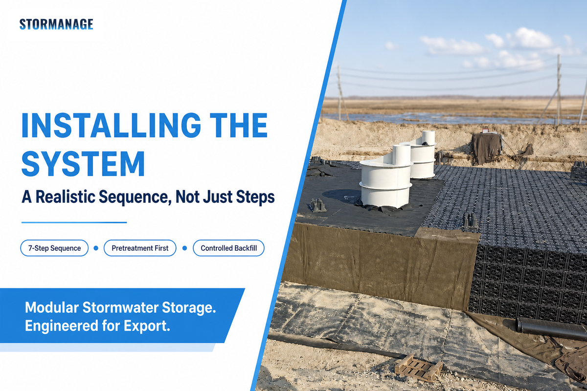
Installing the System: A Realistic Sequence, Not Just the Steps
How to Install an Attenuation Tank
Installation, which happens in a rigid sequence, mostly takes for granted that everything at the Six-Stage sign-off level has already happened before anyone starts digging the first shovel of dirt. The CIRIA SuDS Manual (C753) construction assessment checklist covers this same sequence in more formal language, for anyone who needs to hand a contractor a citable reference rather than just a blog post.
Installation sequence, tied back to the sign-off stage that fixed each decision:
Excavate to the confirmed depth (set in Stage 1, site assessment)
Install pretreatment upstream of the inlet
Lay the bedding layer
Assemble and interlock the crate modules
Wrap in geotextile or a welded membrane (wrap selected in Stage 2, infiltration testing)
Connect inlet and outlet pipework (grade selected in Stage 4, specification)
Backfill in controlled lifts
Any contractor digging before the decisions on all that’s settled is responsible for most of the changes and cost overruns that pop up on these projects. On one sports-field scheme, excavation started against an assumed 400mm module height before the infiltration test came back, which then ruled out soakaway and forced a sealed attenuation build needing the deeper 500mm module and a re-dig of an already-backfilled trench – the two-week delay and re-excavation cost more than the entire pretreatment package would have. Skimping on pretreatment is the most common shortcut, and usually the most painful one downstream: a catchpit or vortex separator, installed upstream of the tank as the first stage of stormwater treatment, treats stormwater runoff by filtering out the sediment and debris (and any other pollutant carried with it) that would otherwise slowly fill up the storage volume over years, long before anyone at surface level would know it’s a problem, protecting the design volume for the full service life rather than leaving that job to the crate grade itself.
Inspection, Sign-Off and What Adoption Actually Requires
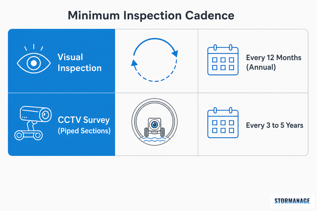
After the initial construction of any system, the scheme can’t be considered complete by most consenting authorities – or even get near to a position where any adoption body will be willing to take over responsibility for its ongoing maintenance – without an inspection history. Our sports, landscape & podium page describes the inspection schedule that a planning authority expects a site owner to maintain, and the CT Stormwater Quality Manual offers a similar baseline that translates well internationally. An annual visual inspection (at least once every 12 months) is the baseline minimum; piped sections also need a CCTV survey every 3 to 5 years, since the internal condition of pipes is unreliable to judge from a visual inspection at the manhole alone.
Minimum sign-off/handover checklist to request from an installer:
Ground-level access for inspection and maintenance confirmed at all points (no confined-space access required)
Upstream of inlet Pretreatment is installed and sized to the catchment
As-built drawings which reflect the trueinvertlevels and the actual connectivity
a scheduled maintenance record (with someone to check, a schedule and cost and billing information).
Who ends up with the paperwork depends on the particular case: if it’s on a system to be taken into water-company care, then it goes into the official handover process similar to Water UK’s Sewerage Sector Guidance documentation stack; if it’s on a podium deck retained by a developer or a privately managed sports facility then it’s likely to remain with the site owner or management company file. Whatever the circumstances, factor jetting and sediment removal into the whole-life cost from the start – a tank which silts up quietly is a tank that will consent its way out long after no-one remembers who put it there.
What’s Changing, England’s 2025 National Standards for SuDS and the Consent Pathway
The UK government introduced new National Standards for Sustainable Drainage Systems in June 2025, explicitly non-statutory, they don’t add a new, standalone, statutory approval process. But that isn’t the same as being optional in practice. When a scheme’s drainage strategy comes before a planning authority and lead local flood authority for pre-application consultation, the standards and destination hierarchy it lays out will be considered against the scheme’s stormwater requirements.
⚠️Important
A designer still has to work through the legal framework that sits across several existing acts, among them the Flood and Water Management Act 2010 and the Building Regulations 2010. These 2025 standards function as the design and evidence layer underneath those approvals, not a replacement for them.
If a sport, landscape or podium scheme, the pragmatic action is simple; consider your present destination hierarchy and evidence test requirements at the pre application stage; not presuming a previous ‘approach to consent’ that applied a couple of years ago still holds good today. Case-by-case consideration of schemes referencing these standards is still underway in 2026; a scheme which pre-populates their hierarchy justification and stormwater management plan to accompany their initial submission will typically proceed quicker through consultation than one attempting to fill these gaps after receiving queries in the first submission.
One honest caveat on the numbers:
The total market size for the broad category of stormwater storage is a public estimate made by several different commercial research firms referencing each other that doesn’t help buyers take action.
This regulatory change is actually the development we should really focus on in project planning for 2026.
Frequently Asked Questions
Q: What is the typical lifespan of an attenuation tank?
View Answer
Storm Manage manufacture StormGrid modules rated for a 50 year service life and this figure relates to the de-rated design allowable load not the tested raw strength – they both have relevance, not one in isolation. Service life figures are variable between manufacturers and grades – check with any potential supplier about what design-life figure they are using rather than assuming a single figure applies universally. Systems that lack a scheduled maintenance regime typically start to demonstrate some reduction in storage volume from sediment within the first 10 years well before there’s any physical damage to the tank – hence the importance of a structured maintenance and inspection schedule (as outlined in the guide previously).
Q: Why do stormwater detention systems need pretreatment?
View Answer
Without any pretreatment, sediment and any other material washed into the system with the runoff accumulates inside the storage zone, filling usable space, blocking flow control orifices, and complicating maintenance access as it is distributed throughout the system instead of being consolidated within an accessible catchpit or vortex separator. By concentrating all such material at an earlier stage, prior to the storage modules themselves, a system can be kept functioning at the design volume for the entirety of its intended service life rather than losing volume progressively without notice.
Q: What are the common problems with attenuation tanks?
View Answer
The two main problems encountered with silt is accumulation of which there’s no evidence during normal operation, because no access points were included in the original design to enable visual inspection and, second, flotation/buoyancy issues on sites where there is a high water table (high groundwater), and where an empty tank could float free from its foundations unless designed to resist uplift. Both can be dealt with during the design and specification phase and become extremely expensive if they’re only encountered once the project is complete and has been buried over.
Q: How far away from a building must an attenuation tank be installed?
View Answer
The proximity required is a function of tank depth, overlying ground cover and foundation design to the building, i.e., less cover to shallow tanks requires greater proximity. Again, this is a structural engineering matter on a specific site, and cannot be provided as a fixed rule of thumb applicable across the board.
Q: Do I need planning permission for underground stormwater storage on a sports, landscape or podium project?
View Answer
In many local authority areas any significant development where impervious area increases would involve a stormwater or surface water drainage consultation as part of the planning approval. Underground storage alone rarely represents a stand-alone permission trigger, but the overall drainage strategy would certainly do so. England’s National Standards for SuDS, published in June 2025, reference a destination hierarchy and an evidence requirement, and a scheme that provides a justification for the hierarchy adopted along with a maintenance plan at the pre-application stage would generally have fewer follow-up questions from consultation authorities than one submitting a simple volume calculation. Local authority specific criteria can be found from your planning department or flood authority, who set the drainage triggering threshold for their area. Worth noting: this is the same pre-application evidence pack the Six-Stage sign-off map builds toward – the five spec lines a supplier needs to quote (catchment, consented discharge rate, depth, grade/load case, adoption status) and the hierarchy justification a planning consultation asks for overlap by design. A buyer who assembles one has, in practice, already assembled most of the other, which is why front-loading that paperwork at pre-application tends to move a scheme through consultation faster than treating the drainage submission and the supplier tender as two separate, sequential jobs.
Q: Can storage be installed under an existing sports pitch, or only during construction?
View Answer
It’s possible to retrofit underground storage below a new pitch – but it’s a much more disruptive option than designing into a new build – not least because the surface needs to come out of play for the entire excavation and backfill, and the retrofit will have to take place around an existing collection layer rather than being designed into the scheme. In situations where the budget permits, piggy-backing storage retrofit onto a planned resurface or refurbishment of a pitch will be a more economical option than under taking it on a stand-alone basis.
We’ve created this guide because the question we receive more often than any other from buyers for sports, landscapes and podiums isn’t “which crate grade should I buy?”, but “who do I need to get to sign off on this before I can even ask that question?” Here’s the sequence we’ve found to work on live projects, not a generic install manual.
Facility
8,000 m² injection-moulding plant near Yantian Port, Shenzhen
Capacity
8 machines, 1,000 tons to 2,000 tons clamping force, 12+ mould sets (400 mm to 500 mm module heights), 60,000 m³+ crate volume per year
Storm Manage manufactures the StormGrid geocellular crate systems – modular systems designed to interlock on site, and one of several stormwater management solutions in wider use across dense urban areas – referenced on our sports, landscape and podium solutions page.