We use the details you submit to review and respond to your project enquiry. Entries are handled in this website’s WordPress database using Fluent Forms; our hosting and email providers may process the submitted details. Other technical providers receive only the data described in our Privacy Policy.
Please do not send passwords, payment-card details, government identification numbers, sensitive personal data, or unnecessary confidential third-party information.
October 2026 · Reviewed by the Storm Manage technical team
To maintain attenuation tank, an underground stormwater tank needs to be cleared of silt and have its outlet control discharge surface water at the consented rate. Across the UK, buried cellular modules and concrete vaults, fail not because the structural shell collapses, but because unemptied catchpits and uninspected orifices choke the hydraulic outlet. Specifying inspectable channels and upstream sediment traps before burial can make a blind excavation a serviceable asset.
Quick Specs: UK Attenuation Tank Maintenance Baseline
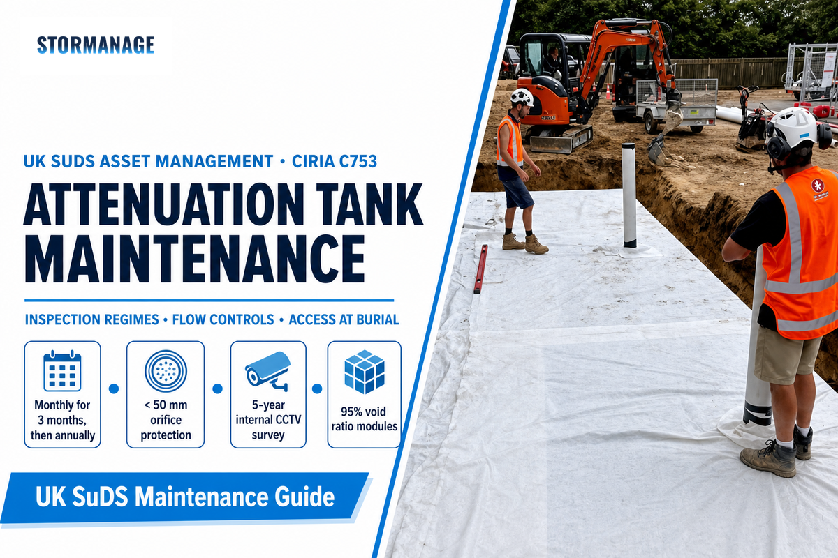
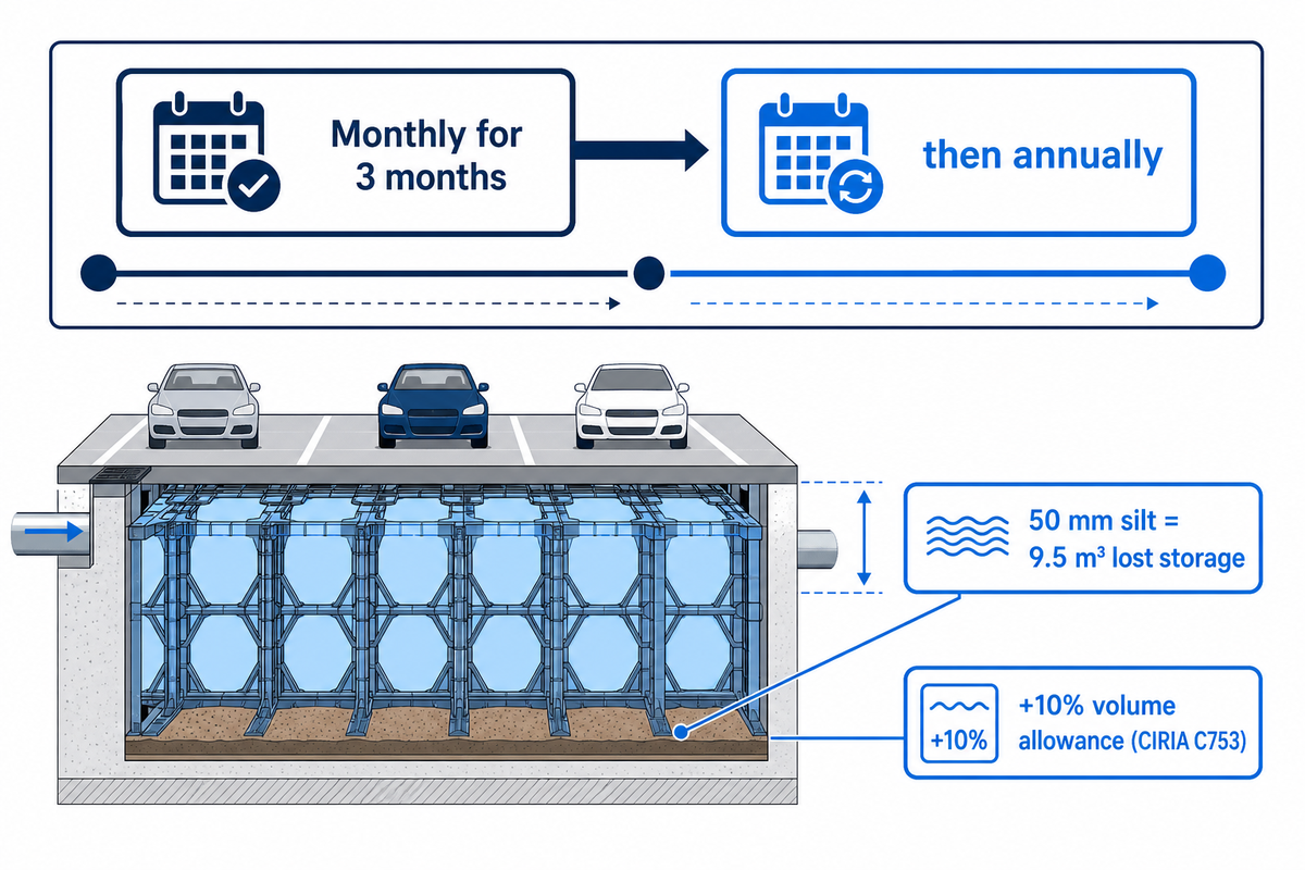
Year-one commissioning checks: Monthly for the first 3 months after installation, then annually (CIRIA C753 Table 21.3).
Catchment & pre-treatment: Remove surface debris monthly. Catchment & pre-treatment: Empty upstream silt traps and forebays internally, annually or at 50% sump depth.
Internal Condition Survey: CCTV survey of the storage volume every 5 years or after a major Storm Surcharge event.
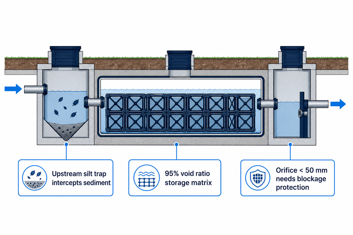
Orifice protection threshold: Flow controls with openings under 50 mm require dedicated blockage protection under Defra Standard 3.22, and all flow controls require blockage risk assessment.
Access rule: Inspect and jet from surface shafts without routine human entry under HSE Confined Spaces Regulations 1997 (L101).
Attenuation tank maintenance keeps underground stormwater storage clear of silt and its outlet flow control discharging at the consented rate. CIRIA C753 Table 21.3 sets monthly checks for three months, annual inlet and outlet inspections, and five-year internal surveys. Pair upstream catchpits with surface access.
Key Takeaways.
A crate or concrete vault provides storage volume only. Hydraulic attenuation is provided by a flow control and requires the closest inspection.
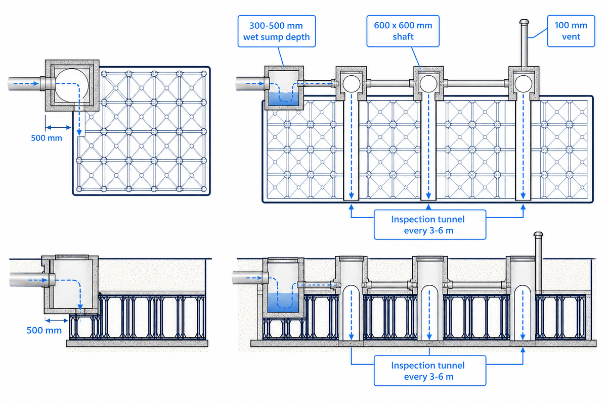
Perimeter manholes alone can’t pass a camera or jetting hose across a multi-crate matrix, unless continuous internal inspection channels are aligned with the shafts at design.
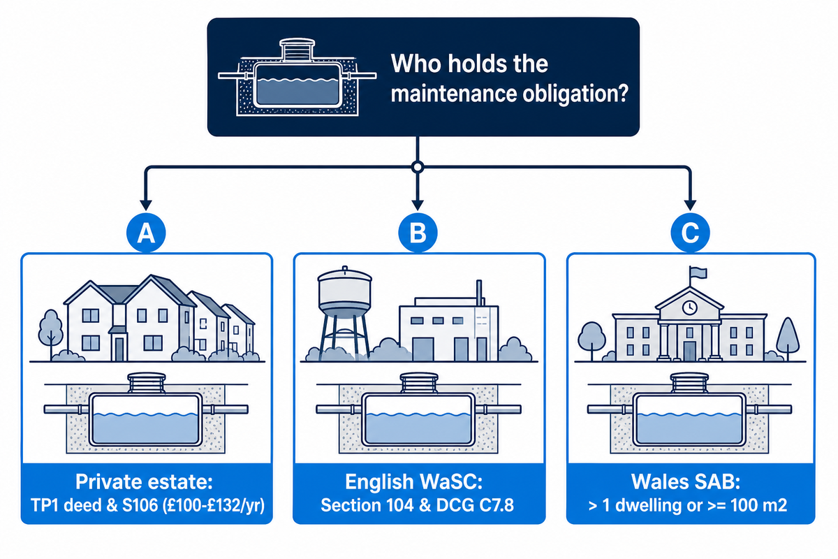
Water and sewerage companies in England frequently decline Section 104 adoption of geocellular tanks used purely for attenuation, leaving long-term upkeep with the property owner or estate management company.
Defra’s June 2025 National Standards for Sustainable Drainage Systems (Standard 7) state that for new developments, a Lifetime Maintenance Plan and surface-visible blockage indicators must be part of the planning submission.
What Stormwater Attenuation Tank Maintenance Covers, and Why the Outlet Matters Most
The three basic functions of Stormwater attenuation tank maintenance are: intercepting sediment before it enters the buried storage zone, ensuring the outlet flow control discharges at its consented litre-per-second limit, and keeping inspection logs for the approving authority. If the outlet isn’t confirmed, then a blocked orifice results in controlled storage becoming upstream gully flooding.
5 Yearsmaximum interval for internal sediment survey (CIRIA C753)
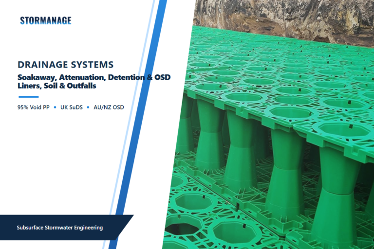
95%void ratio in StormTank H400 and H500 modules
For heavy rainfall events, Engineers classify underground attenuation tank systems as engineered structures designed to temporarily store excess rainwater, and release it at a controlled rate, downstream. In modern underground stormwater management, these stormwater management systems are central to managing stormwater runoff across paved development. Unlike an unlined soakaway that’s dependent on soil infiltration, a sealed stormwater attenuation tank encapsulates its storage matrix with an impermeable geomembrane and thus water can exit only by means of the downstream outlet. The performance of the buried modules depends on two boundary conditions. The first of these is the pre-treatment chamber which captures sand and leaf litter. The second of these conditions is the downstream flow control chamber which meters the discharge.
According to Water Magazine’s October 2024 technical guidance on avoiding underground SuDS attenuation failure, post-construction handover surveys and snagging checks are frequently omitted when civil contractors demobilise. Construction-phase clay, mortar washings, and road sub-base fines wash straight into the primary silt trap during the final weeks of paving. Without effective stormwater management at handover, that initial plug of construction debris migrates into the storage void during the first autumn storm, blinds the lower crate layer, and raises the risk of flooding.
Do attenuation tanks need maintenance?
Yes, every underground attenuation tank requires scheduled maintenance because upstream runoff carries suspended silt, tyre crumb, and leaf litter that settle inside chambers and obstruct outlet controls. Even though polypropylene geocellular crates resist biological decay for 50 years, the hydraulic system around them fails within 12 to 36 months if silt traps overflow into the main tank or debris jams the outlet orifice.
Suppliers who describe buried plastic crates as maintenance-free are referring only to the inert polymer skeleton, not the working drainage system. Under Defra’s 2025 National Standards for Sustainable Drainage Systems (Standard 7), every sustainable drainage asset must have a documented operation and maintenance regime covering the lifetime of the development. When nobody empties the upstream catchpit, sediment builds up across the tank floor, steals active m³ of attenuation storage, and forces storm runoff to surcharge through car park gullies during heavy rainfall.
Section Takeaway: Treat the buried tank as a passive reservoir bounded by two active service points. The upstream silt trap intercepts sediment. The downstream flow control chamber controls the removal of sediment from the site.
The 9-Stop Inspection Walk: What to Check From Inlet to Outlet
The 9-Step Inspection Walk sequences attenuation tank maintenance from the paved catchment to the outfall to allow drainage technicians to trace sediment transport in the direction of flow. Following a fixed 9-step path with specified action thresholds prevents contractors from declaring the entire system serviceable after lifting a single manhole cover.
9-Stop Inspection Walk: This describes a nine-point field assessment process for checking a buried stormwater attenuation system from the uppermost layer of surface paving to upstream treatment, storage, and control structures, as well as outlet controls, and downstream outfall.
The majority of drainage call-out sheets fail because an operative checks the silt trap without opening the outlet chamber or jets a pipe without measuring to see if the water level dropped between storms. Site managers can simply copy the nine row schedule below and include it in their annual service specification. Each of the nine stops describe a physical check, an instrument or means to check, a numerical or observable indicator to trigger remedial work, and the party responsible for such work.
Table 1: The 9-Stop Inspection Walk (Inlet-to-Outlet Field Protocol)
Stop
Component & Location
Inspection Method
Act When (Trigger Threshold)
Responsible Party
Limitations / Not Suitable For
1. Surface footprint
Asphalt, block paving, or turf above tank
Visual walkover and straight-edge check
Surface depression > 15 mm, cracked frame, or standing water 24 h after rain
Facilities manager / caretaker
Surface level checks cannot detect sub-base washout under rigid concrete slabs until voiding widens
2. Catchment inlets
Road gullies, linear channel drains, roof shoes
Lift grates and dip gully pots with graduated rod
Grate leaf blinding > 25% area or gully sump sediment > 50% wet depth
Grounds maintenance team
Clearing grates alone does not remove dissolved hydrocarbons from car parks
3. Pre-treatment unit
Upstream silt trap, catchpit, or hydrodynamic separator
Sludge dip rod or ultrasonic interface probe from surface
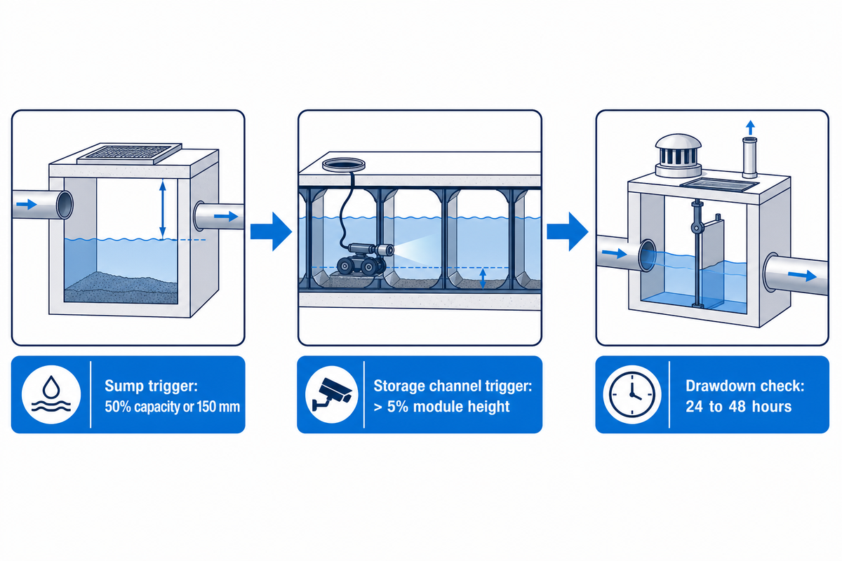
Sediment depth reaches 50% of sump capacity or within 150 mm of outlet invert
Drainage tanker contractor
Standard catchpits do not retain fine clay particles < 63 µm during high-velocity storms
4. Inlet chamber
Manifold header, diffuser pipe, or internal forebay
Surface lamping and pole-mounted zoom camera
Silt benching > 25 mm in header pipe or displaced inlet seal
Drainage inspection technician
Pole cameras see the manifold entry but cannot inspect off-axis crate rows
5. Storage channels
Internal inspection tunnels across crate matrix
Pan-and-tilt crawler drainage CCTV survey coded to BS EN 13508-2
Silt accumulation > 5% of module height (e.g. > 25 mm in 500 mm crate) or strut distortion
Specialist CCTV survey crew
Impossible on non-inspectable crate blocks built without dedicated internal tunnels
6. Air vents
High-level air release pipes and cowl grilles
Visual check of vent cowls and smoke or airflow test
Insect mesh blocked, pipe crushed, or cowl buried under landscaping mulch
Facilities maintenance technician
Blocked vents trap air pockets that restrict inflow even when the inlet pipe is clean
7. Overflow route
High-level bypass weir, flap valve, and exceedance path
Check weir crest clearance and hinge movement
Trash screen > 20% fouled, flap hinge seized, or overland route obstructed by fencing
Site operator / drainage engineer
Dry-weather checks do not verify tailwater surcharging in the receiving sewer
8. Flow control
Vortex flow control device or simple orifice plate
Visual inspection from surface, calliper check of opening, pull-cord test
Any ragging, gravel wedged in intake, missing screen, or standing water above invert 48 h post-storm
Drainage maintenance contractor
Submerged controls cannot be inspected visually until the upstream bypass or penstock is isolated
9. Final outfall
Downstream connection to sewer or watercourse headwall
Check headwall grille, non-return flap, and bank scour
Outfall submerged by watercourse silt, bank erosion > 100 mm, or flap wedged open
Asset owner / adopting body
Downstream public sewer surcharging requires water company coordination
Stops 6, 7 and 8 are related to each other and are particularly important during a rainfall. If the air release vent at stop 6 is covered with bark, or blocked by vermin, air trapped beneath the geomembrane can’t escape as stormwater runoff enters the inlet manifold. This pressurized air cushion blocks the inflow and causes upstream gullies to flood while the crate tank remains half empty. Checking if water levels dropped to the outlet invert within 24 to 48 hours after rainfall indicates if the flow control device at stop 8 is partially obstructed, and satisfies the surface visibility requirement in Defra Standard 7.16.1.
Section Takeaway: Require your drainage contractor to log a dated photo and measurement of sediment for each of the nine stops rather than submitting an invoice for gully emptying.
How Often Should an Attenuation Tank Be Inspected? Year One vs Steady State
Following initial commissioning, examine a new attenuation tank monthly for three months. Inspect a newly installed attenuation tank monthly for the first three months after commissioning, then transition to monthly catchment debris clearance, annual inlet, outlet, and silt-trap servicing, and a five-year internal tank survey under CIRIA C753 Table 21.3. Additionally, carry out post-storm checks if rainfall exceeds the one in one year design event.
Regular maintenance: Inspect and identify any areas that aren’t operating correctly monthly for 3 months, then annually; remove debris from the catchment surface monthly; check the surface filter where runoff infiltrates from above annually; and remove sediment from pre-treatment structures and internal forebays annually, or as required.
Remedial actions: Repair or rehabilitate inlets, outlets, overflows, and vents as required when routine checks identify displacement or blockage.
Monitoring: Inspect and check all inlets, outlets, vents and overflows annually to confirm free flow and, if necessary, survey the inside of the tank every 5 years and/or as required for sediment build-up and remove if necessary.
Per UK Government flood-risk asset maintenance guidance, baseline intervals should be adjusted for catchment sediment load, site usage and extreme weather triggers. Use the conditional decision matrix below to determine your inspection interval based on your catchment and tank configuration.
Table 2: Conditional Maintenance Regime by Catchment Risk and Tank Configuration
Catchment & Site Risk Profile
Tank Configuration
Year-One Regime (Months 1–12)
Steady-State Routine Regime
Desilting & CCTV Trigger
Limitations / Not Suitable For
1. Clean roof-only commercial building
Inspectable geocellular crate with leaf filter
Monthly for first 3 months, then at Month 6 and Month 12
Monthly roof gutter/shoe check; annual silt trap & outlet service
CCTV every 5 years or if sump silt > 50%
Does not cover wind-blown gravel from ballasted flat roofs without parapet leaf guards
2. Clean roof-only residential block
Non-inspectable standard crate block
Monthly for first 3 months, then quarterly in Year 1
Six-monthly catchpit dip; annual outlet and vent check
Empty catchpit at 40% depth to prevent tank entry
Zero internal jetting recovery if catchpit overflows; requires 10% volume allowance at design
3. Paved residential estate roads & drives
Inspectable geocellular tank + upstream catchpit
Monthly while plots are under construction + 3 months post-surfacing
CCTV every 3 years to check elastomeric joints for root ingress
Willow and poplar roots within 5 m can penetrate unsealed vent connections
8. Phased housing site with active upstream earthworks
Any permanent underground attenuation system
Isolate permanent tank or inspect fortnightly during earthworks
Full jetting, desilt, and CCTV handover survey before final surfacing
Mandatory pre-handover clean regardless of calendar age
Permanent geocellular crates must never act as temporary construction settlement ponds
9. High-groundwater coastal or clay basin site
Geomembrane-sealed tank with anti-flotation design
Monthly for 3 months; check cover levels after first wet winter
Annual outlet, vent, and surface level check; check groundwater standpipe
Never fully dewater sealed tank for cleaning when groundwater exceeds O&M limit
Pumping a sealed tank completely dry during winter high groundwater risks buoyancy uplift
Worked Example (Quantifying Storage Capacity Lost to Silt): StormTank module data specifies H400 1000x500x400 mm = 190 L and H500 1000x500x500 mm = 237.5 L at 95% void, in load grades ST-E20 to ST-H60 (20-60 t/m2). Assumed inputs for our sediment-loss worked example: consider a 100 m³ commercial car park tank built from 421 StormTank H500 polypropylene modules (each 1000x500x500 mm module provides 0.25 m³ gross volume and 237.5 L net storage at a 95% void ratio) arranged in a single 0.5 m layer over a 10 m × 20 m (200 m²) plan footprint. Suppose the upstream catchpit is left unemptied for three winters and a uniform 50 mm (0.05 m) blanket of compacted road silt settles across the tank floor. The lost net storage volume equals footprint area × silt depth × void ratio: 200 m² × 0.05 m × 0.95 = 9.5 m³ of lost attenuation capacity (equivalent to 40 H500 modules or 50 H400 190 L modules knocked out of service, a 9.5% reduction in total storage volume). When upstream sediment capture is down-sized on a hard-to-clean geocellular crate tank, CIRIA C753 Clause 21.5.3 and Table 21.2 advise the designer to increase the crate tank storage volume by 10% up front to offset this progressive capacity loss.
How often should an attenuation tank be cleaned?
Clean the upstream silt trap or catchpit annually or whenever sediment reaches 50% of the sump depth, and clean the main attenuation tank interior only when the five-yearly CCTV survey or post-storm dip shows silt accumulation exceeding 5% of module height. Routine high pressure jetting of a clean geocellular tank wastes the budget and may damage the geomembrane if the nozzle pressure is beyond the limit of the manufacturer.
In the case of well maintained pre-treatment, main storage matrix will be free from sand and grit for decades. The drainage contractor vacuums the upstream catchpit sump in 30-45 minutes, during the annual visit. Full internal tank jetting and vacuum tankering are triggered events, for example, silt contamination prior to handover, catchpit bypass during a storm exceedance event or five-year internal CCTV survey which reveals storage loss.
Section Takeaway: Lock in monthly checks for the first 90 days after installation to catch construction silt. After that, let measured sediment depth in the catchpit dictate when tanker cleanings are needed, instead of relying on arbitrary calendar dates.
The Access-at-Burial Checklist: What to Specify Before the Tank Is Covered
Before backfilling the excavation, install silt traps upstream, align internal inspection channels, and provide surface recoverable flow controls, as well as drawings showing camera reach. Additionally, provide evidence of maintenance limits for jetting in the O&M manual, access for rodding of the outlet chamber, and surface-only maintenance limits.
Access-at-Burial Checklist: Seven clauses coupled with the evidence to demand (Camera-reach drawing, manufacturer jetting limit in O&M manual, outlet chamber rodding access, Surface only maintenance limits) built from client’s StormTank build sequence, UK guidance, prior to burial of an underground tank.
“All parts of the sustainable drainage system to which personnel, vehicles or machinery access is required (including flow controls) shall have free, safe and easy access.”
A recurring error on UK projects is assuming that two perimeter inspection chambers placed at opposite corners of a 300 m³ crate field satisfy attenuation tank design and installation rules. A corner manhole only lets a technician see the end of the distribution pipe; without moulded internal inspection channels aligned directly with the shaft invert, a crawler camera or rotary jetting hose hits a plastic wall 500 mm inside the tank. Providing dedicated access for cleaning across attenuation crates ensures that buried geocellular systems remain serviceable without excavation. Similarly, in Great Britain, Regulation 4(1) of the Confined Spaces Regulations 1997 (HSE Approved Code of Practice L101) requires employers to avoid entry into a confined space so far as is reasonably practicable, for example by doing the work from the outside. Every silt trap, rodding eye, and flow control bypass must therefore be operable from finished ground level.
Where site levels and high silt loads warrant extra protection, configuring an offline attenuation tank layout keeps normal dry-weather and first-flush flows in the main carrier pipe, diverting water into the crate storage only when storm flows exceed the downstream throttle threshold. When specifying a crate system, you must request that the contractor provide a dimensioned camera-reach drawing and obtain the written limit of jetting pressure from the manufacturer. Perimeter manholes without aligned internal channels keep the interior of the manhole blind.
RFQ checklist (copy these into your quote request):
Parameter
Recommended range
Why it matters
How to verify
Upstream silt trap sump depth
Minimum 300–500 mm wet sump below outlet invert
Traps coarse sand and gravel before the tank inlet manifold (Defra Standard 7.14)
Dimensioned chamber section drawing and tanker hose clearance check
Internal inspection channel coverage
Dedicated tunnel row every 3–6 m across tank width
Allows pan-and-tilt CCTV crawler and rotary jetting nozzle to reach the storage footprint
BS EN 124 B125 (pedestrian/car) or D400 (HGV highways/car parks)
Prevents frame collapse and surface rutting under wheel loads and vacuum tankers
Cover schedule stamped with BS EN 124 class matching vehicle tracking plan
Takeaway: Demand a dimensioned camera-reach drawing and obtain the manufacturer’s written limit of jetting pressure prior to accepting a crate price quote. Perimeter manholes without aligned internal channels keep the interior of the manhole blind.
Flow Control Checks: Vortex Units, Orifice Plates and Blockage Risk
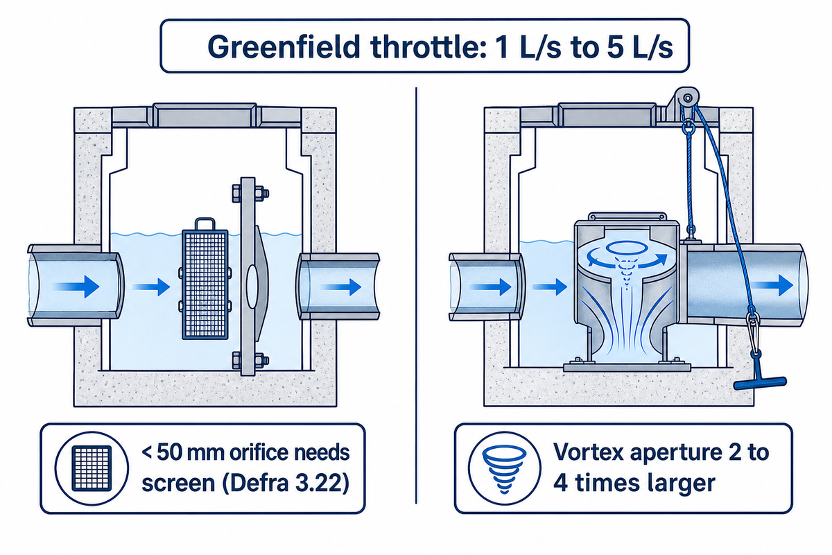
Inspect the outlet flow control chamber annually and after significant storm events to verify the orifice opening, vortex intake, trash screen and emergency bypass cord are clear. Under Defra’s 2025 National Standards (Standard 3.22), orifices less than 50 mm require dedicated blockage protection and every flow control device requires a formal blockage risk assessment.
Why are outlet openings on UK developments so small? Planning authorities commonly restrict post-development surface water discharge to the pre-development greenfield runoff rate, which is often between 1 L/s and 5 L/s on small sites. Passing 2 L/s under a 1.5 m head of water through a simple orifice plate requires a circular aperture well under 50 mm in diameter, which a single plastic bottle, wet wipe, or autumn leaf mat can plug completely.
See the exact language of Defra’s 2025 National Standards for Sustainable Drainage Systems, Standard 3.22: where the peak allowable discharge rate would require the use of a flow control with an orifice (or equivalent) less than 50 mm, the flow control would need blockage protection, and in all cases the risk of blockage for all flow control devices must be assessed and addressed. A hydrodynamic vortex flow control device would achieve the same low litre-per-second discharge rate using an internal air core vortex, and therefore, a physical outlet aperture 2 to 4 times larger than an equivalent orifice plate would be acceptable. A larger outlet passage would help alleviate problems associated with ragging and would require annual checks of the upstream baffle, sump and pull cord bypass.
Do
Fit a removable mesh screen or upstream baffle where an orifice plate opening is under 50 mm in diameter.
Test the surface-operated emergency bypass door or penstock pull-cord at every annual service visit.
Measure standing water depth relative to the outlet invert 24 to 48 hours after heavy rainfall to confirm full drawdown.
Isolate the downstream outlet with a drain plug before jetting the upstream chamber so dislodged grit is vacuumed out, not washed into the orifice.
Don’t
Unbolt, drill out, or remove an orifice plate to clear a flooded car park; removing the throttle breaches the discharge consent and floods downstream sewers.
Leave the emergency bypass flap latched open after desilting the outlet chamber.
Enter a deep flow-control manhole without confined-space gas monitoring and tripod rescue equipment when surface rodding can clear the intake.
Assume a vortex flow control is self-cleaning when construction gravel or builders’ rubble is present in the chamber sump.
Section Takeaway: Always use a vortex flow control or a screened chamber when the consented greenfield throttle pushes a simple orifice plate below 50 mm, and never let a maintenance crew remove the throttle plate to drain a surcharged yard.
Common Attenuation Tank Problems: The Symptom-to-Source Problem Map
Most problems with attenuation tank are caused by upstream silt bypasses, blocked outlet flow controls, air locks, and installation cover mistakes rather than polymer creep in the crates. Mapping visible surface symptoms directly to their hydraulic or structural cause lets facilities teams target the right chamber before commissioning excavation or full-tank jetting.
Symptom-to-Source Problem Map: A nine-row diagnostic troubleshooting matrix that provides observable surface or manhole symptoms of an underground attenuation tank, and describes their underlying hydraulic or structural causes, field verification checks, and corrective actions.
When water backs up through car park gullies or a dip appears in the tarmac above a buried tank, property managers often suspect crate collapse. This is often confused with structural weaknesses or long term polymer degradation. In practice, industry commentary citing CIRIA C737 (Structural and geotechnical design of modular geocellular drainage systems) notes that structural failures attributable to long-term polymer strength are rare when installation follows the structural design; the vast majority of field failures trace back to blocked outlets, neglected silt traps, sub-base compaction defects, or high-groundwater flotation during construction or full dewatering. When a tank is properly designed and installed, proper installation and maintenance prevent premature sub-base settlement and keep the storage matrix open.
Table 3: The Symptom-to-Source Problem Map for Underground Attenuation Tanks
Observable Surface / Chamber Symptom
Primary Hydraulic or Structural Source
Diagnostic Field Check
Corrective Maintenance Action
Limitations / Not Suitable For
1. Tank still holds > 50% water 48 hours after rain stops
Lift outlet chamber lid; compare upstream and downstream water levels across throttle
Pull emergency bypass cord, vacuum out outlet sump, and clear orifice or vortex intake
If downstream sewer side is also surcharged, clearing the orifice will not lower the tank
2. Upstream gullies surcharge during moderate rain while outlet chamber stays dry
Blocked upstream silt trap, silted inlet manifold, or air-locked tank vent
Dip Stop 3 silt trap and Stop 4 inlet chamber; inspect Stop 6 air release vents
Tanker out the silt trap, clear vent cowl mesh, and jet the inlet distribution header
Do not jet high-pressure water into the crate face without checking the O&M bar limit
3. Localised depression or rutting in tarmac above tank footprint
Poor backfill compaction, torn geotextile allowing sub-base fines into crates, or cover depth below spec
Run crawler CCTV through inspection channel beneath dip; check as-built cover depth vs vehicle load
Restrict heavy vehicles over footprint; excavate top capping layer to repair geotextile and re-compact
Top-up tarmac patching hides progressive sub-base loss and increases point wheel loads
4. Tank overflows early in short storms despite clean outlet control
Loss of active m³ of attenuation storage from long-term silt blanket across tank floor
Measure silt thickness via CCTV crawler and dip rods; calculate lost storage volume
Low-pressure rotary jetting along inspection tunnels with simultaneous vacuum tanker extraction
Non-inspectable crate blocks without tunnels cannot be rotary-jetted across the full width
5. Tank never empties completely or refills during dry weather
Punctured welded geomembrane or leaking pipe stub allowing groundwater ingress
Conduct dry-weather level monitoring and CCTV inspection of pipe-to-membrane top hats
Install internal pipe-stub seal or localized patch; verify groundwater table elevation
Permanent groundwater ingress occupies storm storage volume before the storm begins
6. Surface heave or upward cracking over empty tank in wet winter
Hydrostatic buoyancy uplift (flotation) on sealed geomembrane tank in high groundwater
Check borehole/standpipe groundwater level against design anti-flotation calculation
Cease dewatering; engage structural engineer to review ballast overburden or relief measures
Never pump a sealed tank dry for cleaning when winter groundwater sits above the tank base
7. Foul odour or septic hydrogen sulphide smell at car park gullies
Stagnant organic sludge in deep catchpit sumps or cross-connection from foul drain
Gas monitor check at manhole rim; dye-test upstream connections; dip catchpit sludge
Vacuum-empty organic sludge, flush with clean water, and rectify any foul misconnection
Anaerobic silt generates hazardous H₂S gas; strictly prohibit personnel entry without BA
8. Coarse sand and gravel appearing inside downstream outlet chamber
Upstream silt trap sump is 100% full (scouring straight through) or geomembrane/joint breach
Dip upstream catchpit and inspect inlet distribution pipe for joint displacement
Empty upstream silt trap immediately and shorten catchpit desilting interval to 6 months
Ignoring grit in the outlet chamber rapidly abrades and jams vortex and orifice controls
9. Fibrous root mat visible inside vent pipe or inlet header
Tree planted within root zone of unsealed chamber rings or non-welded geotextile wrap
CCTV trace of root entry point at chamber ring joints and pipe spigots
Mechanical root-cutter removal in rigid pipework (not inside plastic crates) and cured-in-place joint seal
High-torque mechanical root cutters will shred polypropylene crate walls if run past the header
What are the common problems with attenuation tanks?
Silt accumulation inside the storage matrix, blocked outlet flow control devices, unemptied upstream catchpits, air-locked vent pipes, and sub-base washout through torn geotextile membranes are the five most common problems with attenuation tanks. During almost every call-out, surface flooding is due to a choked orifice or neglected pre-treatment sump, and not due to a structural failure of the buried crates.
There are two additional issues concerning the cleaning and disposal of tanks. First, Defra Standard 7.15 specifies that contaminated sediment removed from SuDS components requires an Environment Agency permit and cannot be disposed of onsite; under Environment Agency waste classification rules, road-runoff sludge and separator waste must be classified by European Waste Catalogue (EWC) code and transferred only to a licensed waste carrier. Second, on sites with high groundwater levels, emptying a sealed tank during the winter can cause flotation if the water table is higher than the design overburden.
What is the lifespan of an attenuation tank?
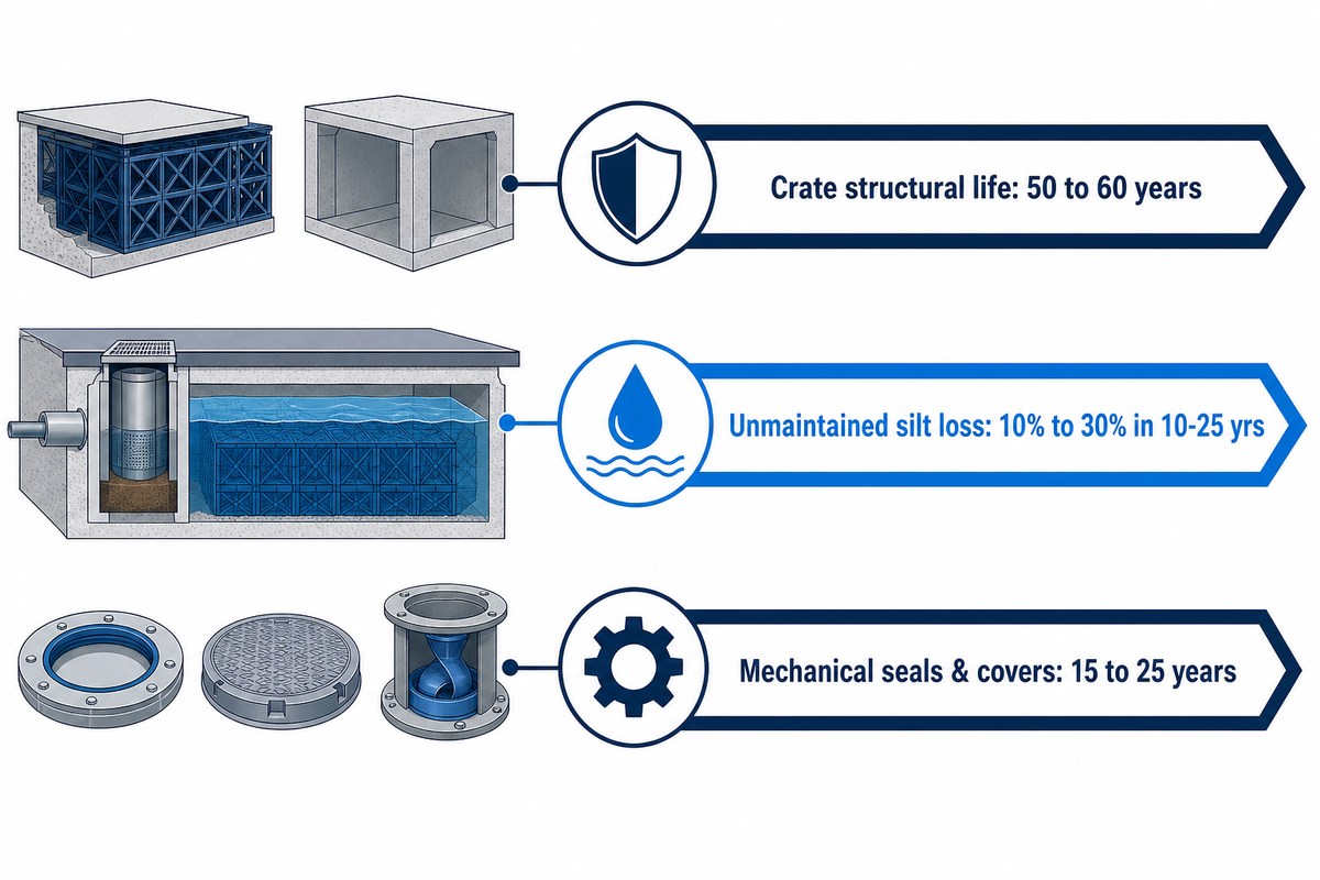
Polypropylene geocellular attenuation tanks carry a standard structural design life of 50 to 60 years (StormTank H400 and H500 modules are specified for a 50-year structural design life), while precast concrete tanks are commonly designed for 50 to 100 years. However, hydraulic storage life is governed by sediment control: an unmaintained tank can lose 10% to 30% of its usable storage capacity within 10 to 25 years if upstream silt traps are never emptied.
Asset owners should separate an attenuation system into three distinct lifespans when writing a whole-life maintenance plan: structural life of the buried crate or concrete shell (50+ years when installed within certified cover depths and traffic loads), hydraulic storage life of the internal void (indefinite when annual catchpit desilting keeps silt out, or curtailed early if sediment is allowed to cake the floor), and mechanical component life of elastomeric chamber seals, ductile iron manhole covers, and stainless steel vortex flow controls (15 to 25 years before seal renewal or cover reset).
Section Takeaway: Recognize the difference between the structural design life (50 years) and the hydraulic storage life of a crate tank; a structurally intact crate still fails its planning condition if silt is trapped in the crate, thus stealing the active water volume.
Geocellular Crates, Concrete or Oversized Pipes: Which Is Easiest to Maintain?
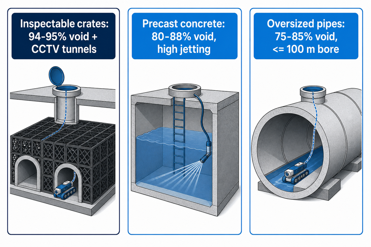
Inspection openings combined with geocellular crates offer the highest internal void ratios (95%) compared to non-inspectable crates. Standard non-inspectable crates should be limited to clean roof catchments with oversized upstream silt traps.
Comparisons of geocellular sub-base systems to concrete tanks, oversized HDPE or concrete pipes, and arched attenuation tunnels often hear the argument that concrete is maintenance-free, and crates can’t be cleaned. There are trade-offs in both statements. Standard pressures in sewer jetting allow oversized precast concrete culverts or pipes to be effectively cleaned, but wide concrete vaults often require confined space entry permits and training (HSE L101) and are most effective when manholes are positioned at each end (within 80-100 m) to give standard reach for hoses.
Conversely, United Utilities’ developer briefing note on geocellular products highlights why water companies scrutinise crate maintainability: standard cellular matrices are not self-cleansing, and high-pressure sewer jetting units risk damaging thin-walled plastic struts if the system lacks dedicated jetting channels. Specifying inspectable geocellular crates with continuous internal tunnels and verifying the manufacturer’s jetting pressure rating bridges that maintainability gap while matching a 95% void ratio to specific project requirements and an access layout tailored to your site. This maintains the balance of the crate system, as it’s designed to do.
Table 4: Maintainability Comparison Across Five Underground Attenuation Storage Types
Maintainability Criterion
Non-Inspectable Geocellular Crates
Inspectable Geocellular Crates (With Tunnels)
Precast Concrete Tanks / Culverts
Oversized Pipes (Concrete / HDPE)
Arched Attenuation Tunnels
1. Void ratio & excavation efficiency
~95% void ratio; smallest excavation footprint
94–95% void ratio (e.g. StormTank 95%); compact footprint
80–88% internal void; heavy cranage and deeper dig
75–85% effective void; long linear trench required
Full length of moulded inspection tunnels via crawler camera
100% open chamber visibility from access shafts
100% linear bore visibility between manholes (≤ 100 m)
100% along open arch row; 0% inside surrounding stone sub-base
3. Jetting pressure tolerance
Not jettable across matrix; header pipe flush only
Low-to-medium rotary jetting within supplier O&M bar limit
High tolerance to standard municipal sewer jetting fleets
High tolerance to standard sewer jetting and drag-bucket cleaning
Arch interior jettable if fitted with lined floor or isolator row
4. Confined-space entry requirement
Surface-only at perimeter shafts (human entry impossible)
Surface-only via aligned shafts (complies with HSE L101)
Often requires confined-space entry for wide flat-floor desilting
Surface-only via upstream and downstream manholes
Surface-only via end manifold access chambers
5. Silt dead-zone & volume allowance
High dead-zone risk; add +10% volume per CIRIA C753 21.5.3
Low in tunnel rows; off-tunnel rows rely on lateral flush + catchpit
Bench floor channels needed to prevent corner silt banking
Minimal dead zones due to circular invert geometry
Fine silt migrating into stone surround cannot be jetted out
6. UK water company S104 adoption stance
Generally refused for adoptable sewer network
Accepted on private schemes; restricted by some WaSCs (e.g. UU)
Widely accepted under DCG Section C7.8 when access is provided
Preferred by water companies for adoptable online storage
Case-by-case review; mainly private commercial/highway use
Section Takeaway: If your tank sits under a trafficked car park on a private commercial or residential site, specify inspectable geocellular crates with continuous internal tunnels and an oversized upstream silt trap; if you require guaranteed Section 104 water company adoption on a public sewer run, check the local sewerage undertaker’s concrete or oversized-pipe preference before freezing the drainage design.
Who Maintains an Attenuation Tank: Owners, Management Companies and Adopters
The legal landowner is responsible for maintenance of a attenuation tank, unless a water and sewerage company, local authority, or private estate management company adopt it. Under Defra’s 2025 National Standards (Standard 7), single-property tanks remain the homeowner’s responsibility, while multi-property developments require a named adopting or management body.
“All tanks must have provision for access for inspection and cleaning and a means of trapping sediment released during cleaning operations.”
Confusion over who pays for attenuation tank maintenance regularly catches out both commercial landlords and new-build homebuyers. Since 1 April 2020, Ofwat’s Code for Adoption Agreements and the Design and Construction Guidance (DCG) have allowed English water and sewerage companies to adopt sewer-like SuDS components under Section 104 of the Water Industry Act 1991. However, adoption isn’t automatic. As United Utilities explicitly states in its developer briefing note, the company won’t currently adopt geocellular products used purely for attenuation on the adoptable sewer network. When a developer installs a crate tank to satisfy planning conditions on SuDS drainage for new developments, the tank is frequently transferred to a private resident management company rather than the regional water company.
Table 5: Who Maintains the Tank? Legal Ownership and Verification Documents
Development Scenario
Responsible Maintenance Body
Document to Check Before Purchase or Handover
1. Single house, self-build, or single commercial unit
Property freeholder (or commercial tenant under FRI lease)
Planning Decision Notice SuDS condition, Title Plan, and Building Control completion pack
Private estate management company funded by resident service charge
Transfer deed (Form TP1), Estate Rentcharge covenants, and Section 106 SuDS Management Plan
3. Multi-unit estate adopted by Water & Sewerage Company
Regional water company (once Final Certificate of Adoption is issued)
Signed Section 104 Agreement (Water Industry Act 1991) and CON29DW drainage search
4. New estate where S104 adoption is pending completion
Developer remains liable during the 12-month maintenance period until vesting
Section 104 bond schedule and pre-vesting CCTV desilting certificate
5. Highway drainage tank serving adopted public road
Local Highway Authority (County or Unitary Council)
Section 38 Agreement (Highways Act 1980) commuted sum and asset register
6. Qualifying development in Wales (> 1 dwelling or ≥ 100 m²)
Local authority Sustainable Drainage Approval Body (SAB) upon adoption
Statutory SAB approval notice under Schedule 3 of the Flood and Water Management Act 2010
Who is responsible for maintaining an attenuation tank on a new estate?
Whoever owns the land or holds the maintenance covenant in Section 106 planning obligation and property transfer deeds (Form TP1) is responsible for maintaining a attenuation tank on a new estate. Unless a regional water company has signed a Section 104 adoption agreement covering the tank, the developer normally transfers the tank to a private estate management company funded by annual resident charges.
A February 2023 UK homebuyer case on the MoneySavingExpert property forum illustrates how this works in practice: buyers purchasing a plot on an estate of more than 100 houses discovered during conveyancing that a buried stormwater attenuation tank lay beneath their garden boundary, while the estate management charge had already risen from £100 per year to £132 per year. Before exchanging contracts on a new-build house or commercial unit, instruct your conveyancing solicitor to request three documents: the approved SuDS Maintenance Plan submitted under the planning condition, the Section 104 adoption drawing showing whether the tank itself is coloured for water-company vesting, and the management company’s sinking-fund budget for five-yearly CCTV surveys and tanker desilting.
Section Takeaway: Never assume the local water company maintains an estate attenuation tank simply because the outlet pipe connects to a public sewer; check the Section 104 plan and TP1 transfer covenants before exchange.
What Attenuation Tank Maintenance Costs, and How to Brief a Contractor
The cost of annual attenuation tank maintenance in the UK is determined by four site variables. These variables are: if routine visits require only surface catchpit emptying or if they require confined space team deployment, the tonnage of vacuum tanker waste disposal, the requirement of traffic management in live car parks, and if the site has internal CCTV. Briefing contractors to a fixed nine stop scope prevents five-fold quote discrepancies.
While upfront capital attenuation tank cost is driven by excavation volume and module specification, whole-life operating cost is dictated by how easily a two-person drainage crew can access the silt traps and flow control chamber. Easy access means lower operating costs. Preventative catchpit desilting delivers long-term cost savings compared with emergency jet-vac tankering after a blockage. Unverified online calculator estimates vary wildly because one contractor prices a 45-minute visual lid-lift and gully dip, whereas another prices a four-person confined-space entry crew, a 4,000-gallon jet-vac combination tanker, and licensed hazardous sludge disposal. Avoid depending on the generic price tag and assess contractors against the six field cost drivers in Table 6.
Table 6: Service Cost Drivers and Contractor Scope Specification
Cost Driver / Contract Element
Low-Cost Design Condition
High-Cost Escalation Factor
Mandatory Deliverable in Contractor Brief
1. Routine inspection & silt dip
Surface-accessible covers in soft verge or quiet bay
Out-of-hours night shift or Chapter 8 road traffic management
Completed 9-Stop Inspection Walk log with dated photos and mm silt depths
2. Vacuum tanker desilting
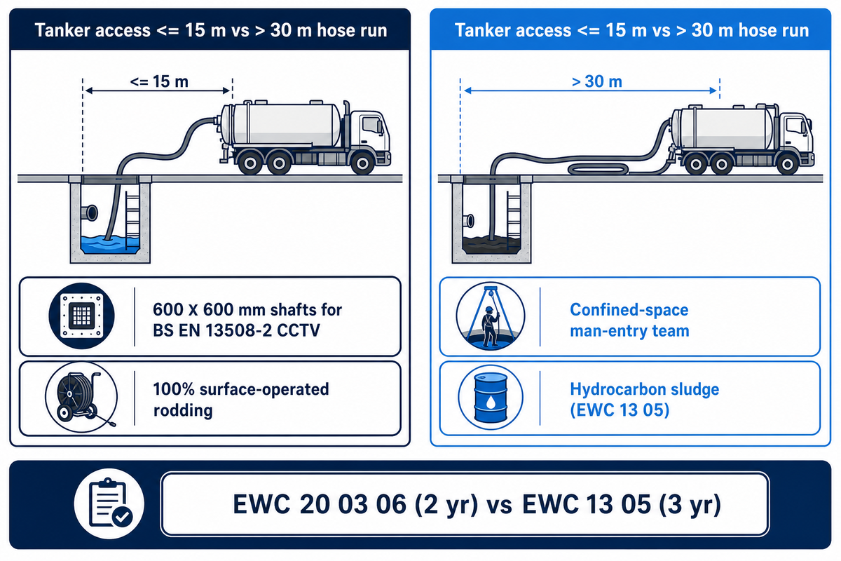
Hardstanding within 15 m of upstream catchpit shaft
Long hose runs (> 30 m) or deep suction lift (> 4 m)
Pre- and post-clean sump depth readings and outlet plug isolation check
3. Five-yearly CCTV survey
Aligned inspection channels with 600 × 600 mm shafts
Blind crate block requiring trial excavation or endoscopic probes
MPEG video + defect report coded to BS EN 13508-2 / WRc MSCC5 standard
4. Confined-space compliance
100% surface-operated bypass, rodding, and jetting
Man-entry into deep chamber requiring tripod, winch, BA, and rescue team
City & Guilds 6150 certification and HSE L101 RAMS where entry is unavoidable
5. Waste classification & disposal
Non-hazardous roof/gully silt (EWC 20 03 06)
Hydrocarbon-contaminated car park separator sludge (EWC 13 05)
Environment Agency Upper Tier Waste Carrier licence + Duty of Care transfer/consignment notes
When issuing a maintenance tender, require every bidder to confirm compliance with Environment Agency waste classification duties and Defra Standard 7.15: wet gully waste and hydrocarbon-contaminated silt removed from car park separators must never be tipped onto site landscaping. Keep every Waste Transfer Note (for non-hazardous silt, retained for 2 years) or Hazardous Waste Consignment Note (for oil-separator waste, retained for 3 years) inside the site’s SuDS Operation and Maintenance file alongside the CCTV survey logs.
Section Takeaway: Standardise contractor quotes by issuing the 9-Stop Inspection Walk, requiring BS EN 13508-2 CCTV coding, and insisting on Upper Tier Waste Carrier transfer notes before work starts.
What’s Changing: The 2025 National SuDS Standards and Your Maintenance Plan
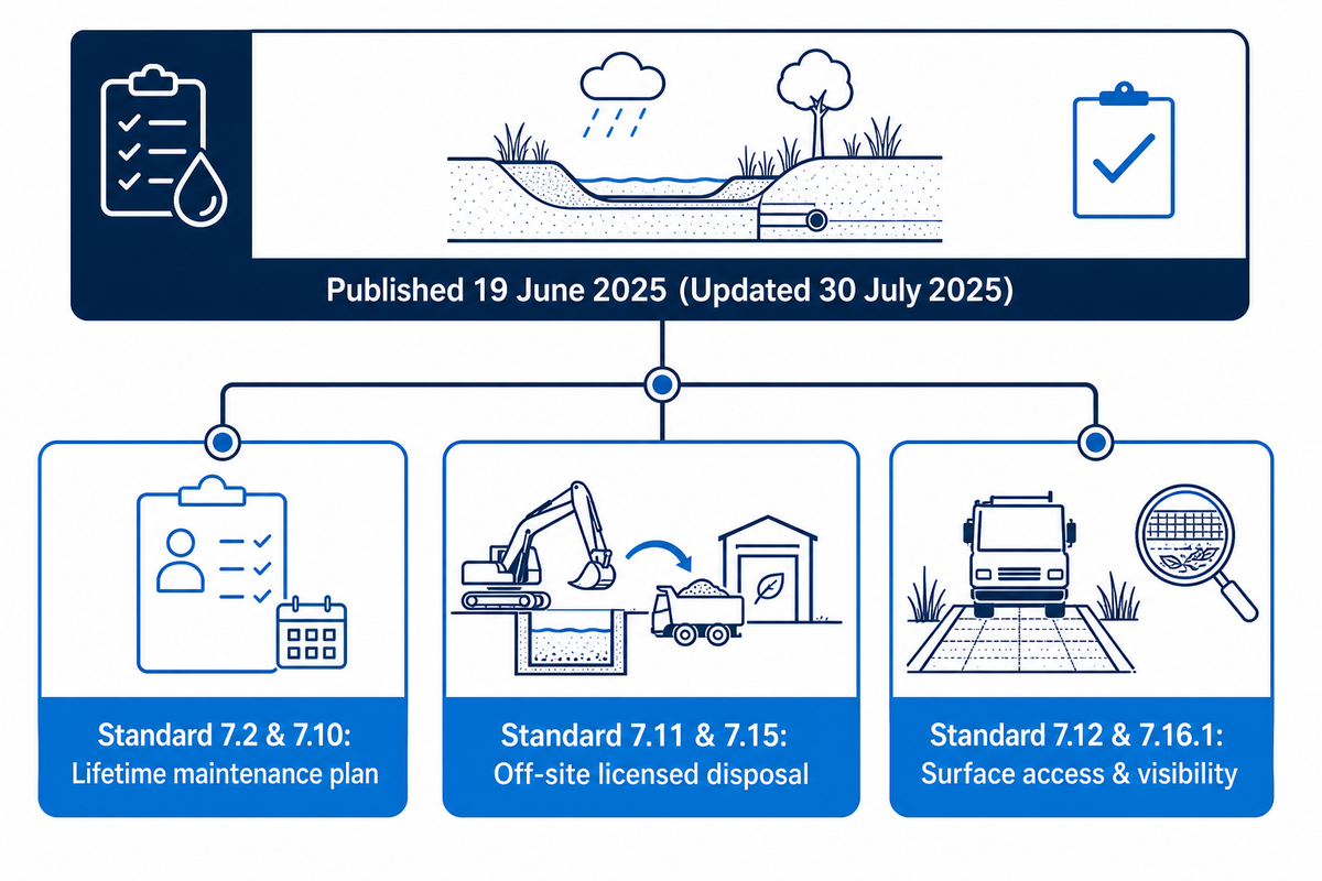
Defra’s non-statutory National Standards for Sustainable Drainage Systems in England, published in June 2025 and updated in July 2025, make a lifetime maintenance plan a core planning approval requirement under Standard 7. These standards don’t mandate the retrospective rebuilding of existing tanks. However, they set the benchmark for the United Kingdom for surface-visible blockage checks and name the maintenance body.
The regulatory direction across the UK market has shifted decisively toward proving maintainability before planning permission is granted. On 19 June 2025 (with a publication page update on 30 July 2025), the UK government published the revised National Standards for Sustainable Drainage Systems for England, replacing the 2015 non-statutory technical standards. In September 2025, as New Civil Engineer reported, the UK government confirmed in Parliament that England will implement sustainable drainage through national planning policy and these updated National Standards as opposed to initiating Schedule 3 of the Flood and Water Management Act 2010 (whereas Wales has operated a mandatory statutory SAB approval under Schedule 3 since January 2019).
For civil engineers, developers, and asset managers reviewing surface water drainage regulations for 2026 project submissions, Standard 7 introduces four specific maintenance requirements that directly shape attenuation tank specification:
Submit a lifetime maintenance plan at planning (Standard 7.2 & 7.10): the designer must supply a management and maintenance plan naming the responsible entities for the lifetime of the development, replacing post-construction hand-waving.
Detail sediment removal and disposal routes (Standard 7.11 & 7.15): the maintenance plan must specify how sediment is trapped, the frequency of removal, and off-site licensed disposal for any contaminated silt.
Prove vehicle and machinery access to flow controls (Standard 7.12 & 7.14): every component requiring tanker or rodding equipment, including buried flow controls and silt traps, must have free, safe, and easy surface access.
Make blockage visible from the surface (Standard 7.16.1): where clogging could cause system failure, the blockage condition must be apparent by visual inspection from finished ground level.
If your existing attenuation tank was built under earlier Building Regulations Approved Document H or CIRIA guidance, the Defra standards of 2025 don’t impose a retrospective legal obligation to excavate your car park. However, should you need to update an estate Operation and Maintenance manual, or should you need to refinance a commercial property, or should you need to prepare a drainage asset for transfer to a management company, an auditable record of compliance with local drainage authority conditions may be satisfied by adhering to Standard 7.11’s inspection schedule and CIRIA C753 Table 21.3.
Key takeaway
Attenuation tank maintenance starts on the drawing board: pair an upstream silt trap and a screened or vortex flow control (≥ 50 mm equivalent protection) with continuous inspection channels so every CIRIA C753 Table 21.3 check can be completed from the surface.
Frequently Asked Questions
Is an attenuation tank a soakaway?
No, an attenuation tank wraps its storage modules in a sealed waterproof geomembrane and releases water through a controlled outlet pipe, whereas a soakaway uses a permeable geotextile to infiltrate water into surrounding soil.
Although both systems often use identical high-strength polypropylene geocellular crates underground, their hydraulic functions and maintenance priorities differ fundamentally. In any attenuation tank vs soakaway comparison, a soakaway vs attenuation tank assessment shows that a soakaway relies on soil percolation tested under BRE Digest 365 and has no downstream outlet pipe, meaning fine silt that reaches the geotextile wrap permanently blinds the soil interface. An attenuation tank is chosen where clay soils, high groundwater, or contamination risks rule out infiltration; it holds surface water runoff temporarily and meters it through a vortex or orifice flow control device into a sewer or watercourse.
Are attenuation tanks maintenance free?
No underground attenuation tank is maintenance-free; while polypropylene crates do not rot or corrode, the upstream silt traps, vents, and downstream flow control device require scheduled annual servicing.
Claims that buried crate systems require zero upkeep confuse material durability with hydraulic serviceability. Road grit, roof moss, and leaf litter wash into the drainage network during every storm event. Under CIRIA C753 Table 21.3, operators must clear catchment debris monthly, inspect inlets, outlets, vents, and overflows annually, empty pre-treatment silt sumps annually, and conduct an internal sediment survey every five years. Neglecting those tasks blocks the outlet throttle and causes rapid surface flooding.
Do I need a maintenance plan for planning permission?
Yes, Lead Local Flood Authorities in England and Sustainable Drainage Approval Bodies in Wales require a site-specific SuDS management and maintenance plan before discharging drainage planning conditions.
Under Standard 7 (paragraphs 7.2, 7.10, and 7.11) of Defra’s June 2025 National Standards for Sustainable Drainage Systems, the submission must identify who will maintain the attenuation tank for the lifetime of the development, specify inspection and sediment-removal frequencies, confirm safe surface access for vacuum tankers and CCTV equipment, and detail how removed silt will be lawfully disposed of off-site. Projects in Wales face a mandatory statutory approval gate under Schedule 3 of the Flood and Water Management Act 2010 before construction can begin.
Can vehicles drive over a buried attenuation tank?
Yes, vehicles can drive over a buried attenuation tank provided the crate compressive strength, minimum soil cover depth, sub-base pavement build-up, and BS EN 124 manhole cover class are engineered for the specific axle load.
Heavy vacuum tankers visiting the site to empty silt traps impose concentrated wheel loads right next to manhole shafts. Always verify the approved construction drawing before routing a 26-tonne or 32-tonne jet-vac tanker across landscaped turf or light-duty pedestrian paving above a tank engineered only for passenger cars.
What happens to an attenuation tank in high groundwater?
High groundwater exerts upward hydrostatic buoyancy forces on a sealed geomembrane attenuation tank, creating a risk of flotation heave when the tank is empty unless the structural design provides sufficient soil cover or concrete ballast.
Groundwater affects maintenance in two ways. First, if a welded geomembrane or pipe seal leaks below the seasonal water table, groundwater infiltrates into the tank during dry weather and occupies storm storage volume before rainfall even starts, which shows up during the 9-Stop Inspection Walk as persistent standing water. Second, during maintenance cleaning, operators must never pump a large sealed tank completely dry during winter high-groundwater periods without first checking the Operation and Maintenance manual’s anti-flotation constraints.
Who approves attenuation tank designs in the UK?
Approval is split across the local planning authority (advised by the Lead Local Flood Authority), Building Control under Approved Document H3, the receiving water company or Environment Agency for discharge consent, and the SAB in Wales.
Each body checks a different aspect of the drainage design. The Lead Local Flood Authority reviews hydraulic sizing modelled against local rainfall data (using the Flood Estimation Handbook and MicroDrainage or similar software) and the lifetime maintenance plan; Building Control checks building setbacks and structural compliance; and the water company assesses Section 104 adoptability or Section 106 sewer connection flow rates.
Specify Maintainable Stormwater Attenuation Storage From Day One
Planning a commercial car park, housing development, or industrial drainage scheme? Storm Manage supplies high-void polypropylene StormTank H400 (190 L) and H500 (237.5 L) geocellular modules with 95% void ratio and 50-year structural design life. Send your engineer’s hydraulic schedule and footprint drawing through our technical enquiry page to review module layout and inspection access provisions.
About This Analysis
This technical guide was prepared and reviewed by the Storm Manage technical team using UK primary regulatory and engineering sources: Defra’s June/July 2025 National Standards for Sustainable Drainage Systems (Standards 3 and 7), CIRIA C753 Table 21.3 maintenance schedules (verified via Kirklees and Welwyn Hatfield local planning records), HSE Confined Spaces Regulations 1997 (L101), and United Utilities’ Section 104 developer guidance on geocellular attenuation tanks. Storm Manage manufactures and supplies modular geocellular storage components; project-specific hydraulic modelling, structural cover calculations, and flow-control sizing must be signed off by the appointed civil or drainage engineer.