We use the details you submit to review and respond to your project enquiry. Entries are handled in this website’s WordPress database using Fluent Forms; our hosting and email providers may process the submitted details. Other technical providers receive only the data described in our Privacy Policy.
Please do not send passwords, payment-card details, government identification numbers, sensitive personal data, or unnecessary confidential third-party information.
Difference Between Soakaway and Attenuation Tank (UK)
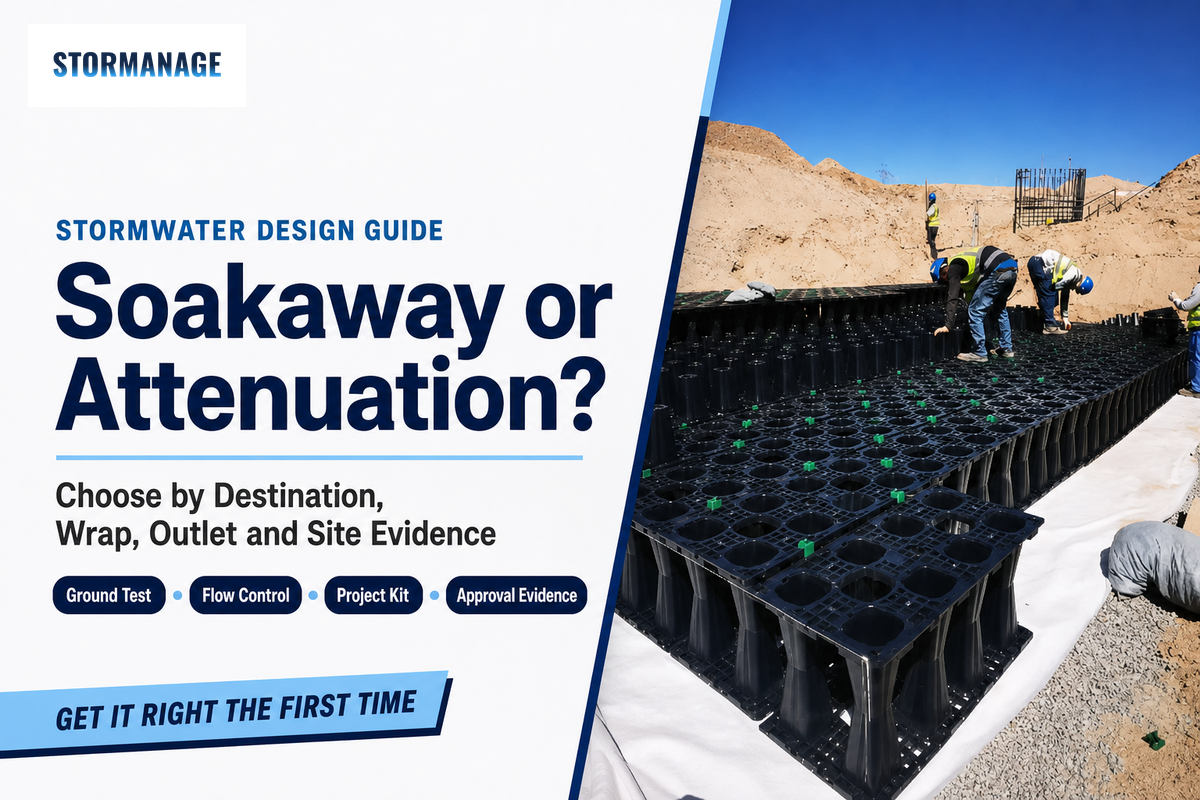
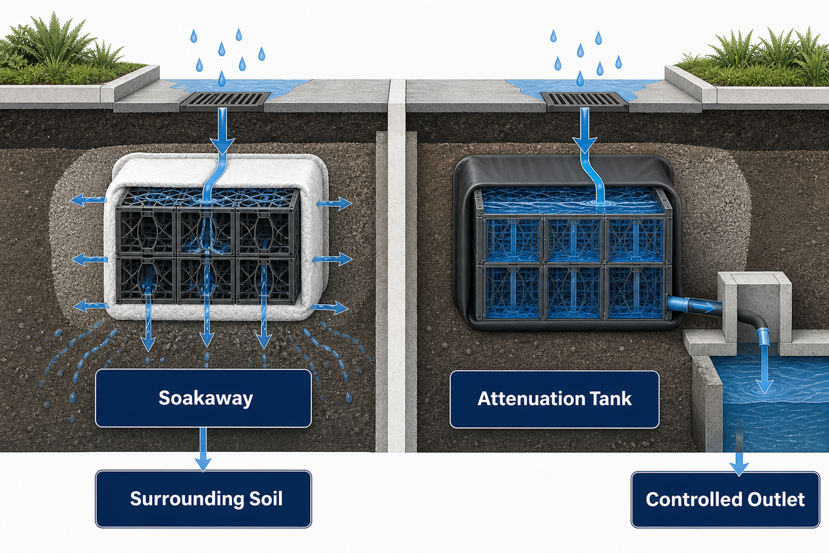
The difference between soakaway and attenuation tank configurations is the runoff destination. In the two standard configurations, a soakaway infiltrates surface water through a permeable wrap, while an attenuation tank stores runoff behind an impermeable liner and releases it at a controlled rate through an agreed outfall. Hybrid, overflow and multi-destination systems exist, so confirm the drainage strategy as well as the physical build. Storm Manage supplies project configurations for both soakaways and attenuation systems; exact crate model, load class, wrap and accessories are project-specific.
Soakaway or attenuation tank: where the water actually ends up
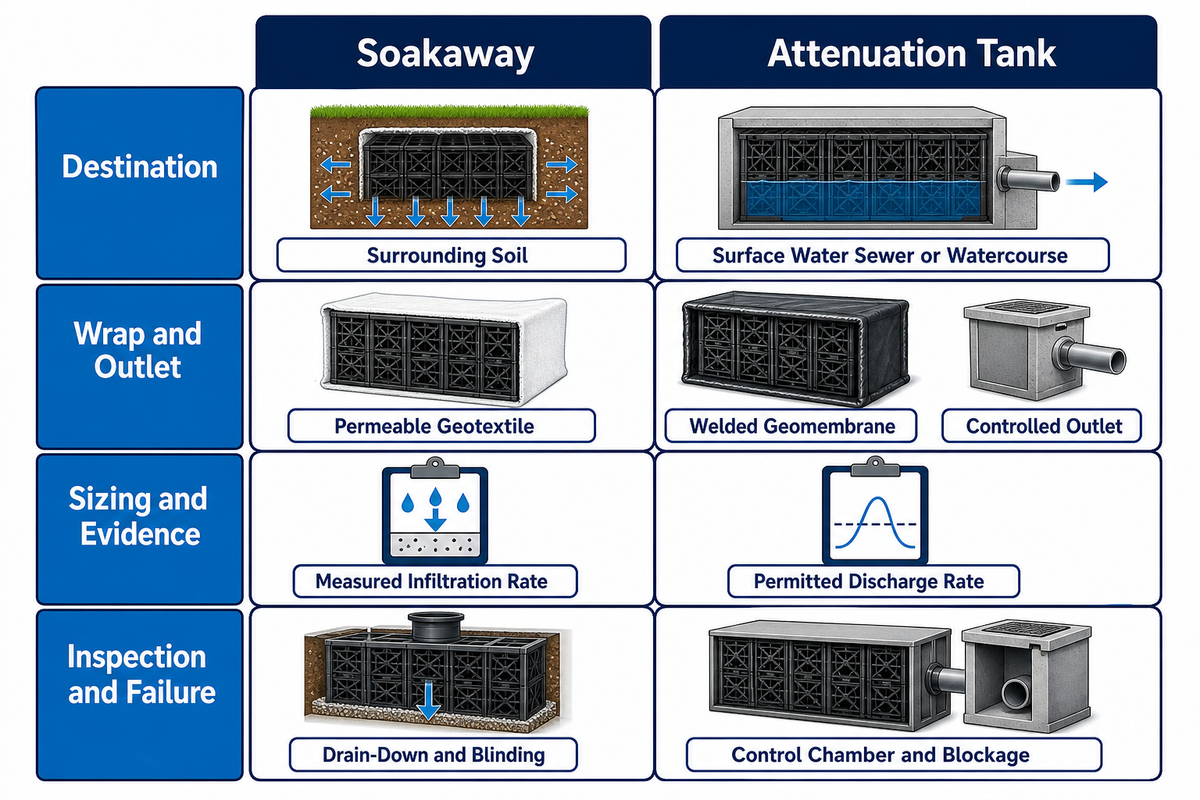
Destination is the whole difference. A soakaway tank sends surface water down into the surrounding soil, where it remains on site. An attenuation tank holds that water back, then passes it on at a rate the receiving sewer or watercourse can accept. Both are underground systems for managing stormwater; only one disposes of it.
Storm Manage supplies project configurations for both soakaways and attenuation systems; exact crate model, load class, wrap and accessories are project-specific. The drainage purpose is determined by the project design, including the wrap and outlet. Excavation, bedding, geocellular modules and cover depth still have to follow that design.
A surface-water soakaway is not a septic tank. It receives roof, driveway or car park runoff for infiltration, while a septic tank belongs to a foul-water treatment regime. Keeping the evidence separate helps reduce the risk of applying a foul-drainage test to a surface-water design.
The Wrap-and-Outlet Test: how to tell which system you are looking at
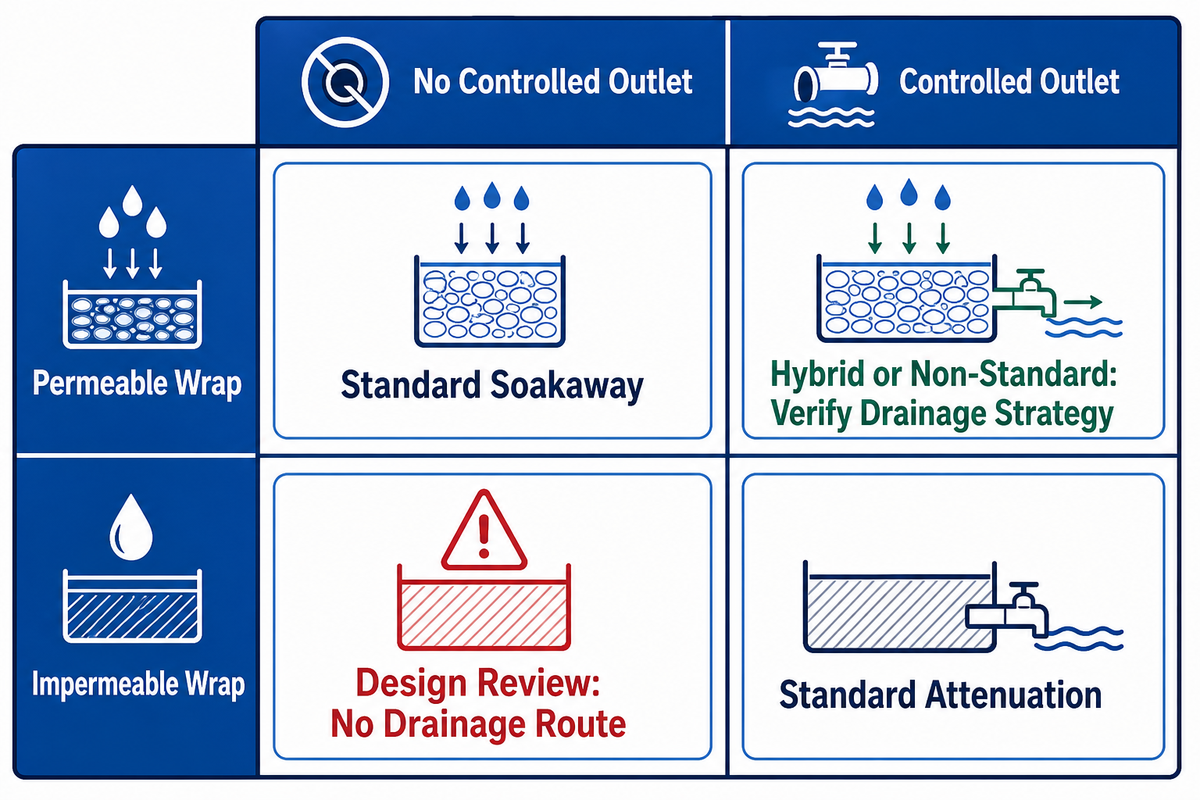
Two questions classify a standard crate-field build on site. Question one: how are the crates wrapped? Question two: is there an outlet pipe fitted with a flow-control device? A permeable geotextile membrane points to infiltration, while a welded liner points to storage. Answering both gives four common outcomes; where they do not match the approved drainage strategy, they are design-review flags rather than automatic build errors.
Wrapped in permeable geotextile
With no outlet, you are looking at a soakaway. Water leaves through the permeable membrane into the surrounding ground.
For a conventional fully controlled-discharge layout, a permeable wrap with an outlet and flow-control device is a design-review flag: the project drainage design should explain the intended route and diversion arrangement.
Wrapped in welded impermeable geomembrane
With an outlet and a flow control device, you are looking at an attenuation tank. Water leaves through the controlled outlet.
For a system intended to drain between events, a sealed box with no outlet is a Design Review: No Drainage Route: the project drainage design should explain how capacity is recovered.
Apply the test as a diagnostic rather than conclusive proof. A controlled outlet indicates storage but does not settle the classification on its own. Partial infiltration, controlled overflow and multiple final destinations can be intentional when the hydraulic design documents them. If the wrap and outlet appear to conflict, check the drainage strategy before calling the build wrong. See the related wrap and flow control guide.
How a soakaway system works, and what it needs from the ground
Soakaway design is a bet on ground conditions rather than a product choice. Rainfall enters the underground storage void and infiltrates into the surrounding soil at whatever rate that soil allows. Excess rainwater that the soil can’t take simply backs up the inlet and surcharges at the surface.
Granular fill and geocellular crates provide different usable storage because their specified material void ratios differ. Where the required net storage is the same, the selected product has a higher declared void ratio and other excavation constraints are comparable, a geocellular tank may require less excavation. In the worked examples below, 95% is an explicit project-specific assumption for illustration, not a market-wide specification.
Emptying speed matters as much as capacity. Royal Borough of Windsor and Maidenhead guidance expects the half-drain time of an infiltration feature to be within 24 hours of the end of a 1 in 30 (3.3%) event including climate change; this is a local criterion, and each project must use its applicable acceptance criteria. A longer drain-down time can leave less capacity for back-to-back storms or heavy rainfall. Silt blinding can slow infiltration and extend drain-down time in soakaway schemes. See the related soakaway crate page.
How an attenuation tank works, and why it needs flow control
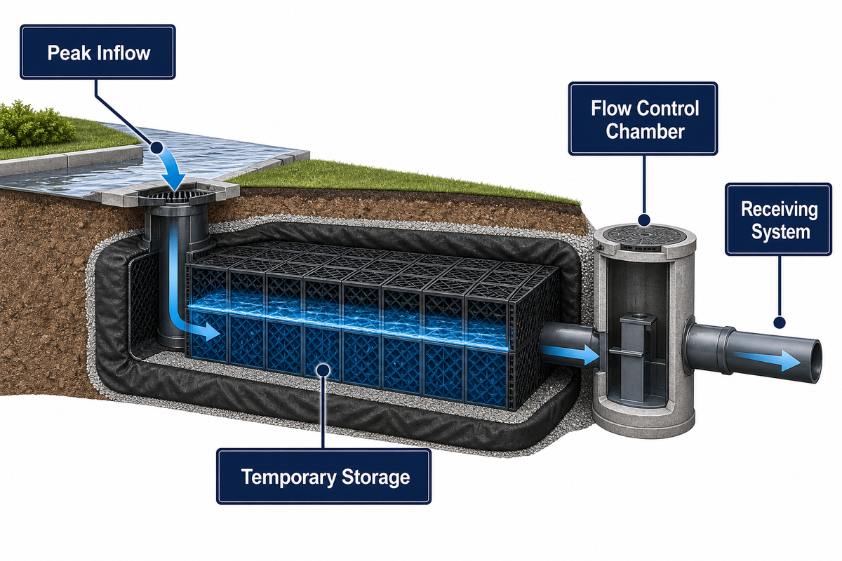
Stormwater attenuation tanks primarily address a discharge-rate problem by providing temporary storage. These storage tanks temporarily hold runoff from a catchment during peak inflow, then allow water to pass through an orifice plate or vortex device. The permitted flow rate controls the rate at which water leaves; required storage follows from the inflow hydrograph, permitted outflow and other project assumptions.
The approved drainage design determines the flow path and diversion arrangement. Compare online and offline layouts with the coordinated site space; the drainage designer selects the final arrangement.
Attenuation tanks used to manage surface water are project-specific underground storage systems. In an attenuation tank installation, the coordinated hydraulic design determines how water is discharged and which inlet, outlet and control details apply. The terms online attenuation system and offline attenuation system describe alternative project layouts; the drainage designer should confirm the intended flow path. An attenuation tank with rainwater harvesting is a combined-use configuration and needs its own hydraulic, water-quality and control design.
Orifice size is a practical constraint on controlling the flow at the source. A permitted discharge of a few litres per second may imply a small opening, so blockage risk must be assessed. US 8,555,924 B2 describes one vortex flow-control device in which, once the pressure head above it exceeds a certain value, the inflowing water generates a vortex within the housing, restricting outflow; the patent also states that its outlet is less prone to blockage than an equivalent orifice. This is a description of that patent, not a claim about every vortex control. Downstream capacity is the point of the exercise: a river or reservoir, or more usually a surface water sewer in the main system, has a ceiling, and attenuation exists to keep the site below it and to prevent flooding elsewhere. Where the receiving network is already at capacity, the drainage design must assess the residual risk of localised flooding. See the related attenuation tank page.
The Specification Split: soakaway and attenuation compared over 14 parameters
Fourteen design parameters separate attenuation tanks and soakaways once the crates are out of the equation. Use the table as a system-design review aid, paying particular attention to sizing input, site testing and failure modes. The crate structure must still be designed for the project load case using the selected product’s declared properties and the project’s structural build-up.
Parameter
Soakaway
Attenuation tank
Primary function
Disposal into the ground
Temporary storage and timed release
Discharge destination
Surrounding soil
Surface water sewer or watercourse
Wrap material
Permeable geotextile
Welded impermeable geomembrane
Outlet
None (overflow only)
Mandatory
Flow control device
Not used
Orifice plate or vortex control
Sizing input
Measured infiltration rate (m/s)
Permitted discharge rate (l/s)
Design guidance
Project-approved infiltration test method and applicable drainage guidance
Project discharge criteria and current modular structural guidance
Primary design evidence
Infiltration test at the proposed soakaway position and depth
Agreed discharge criteria and hydraulic calculations
Groundwater assessment
Apply the approving authority’s criterion; the cited local guidance requires the soakaway base to be at least 1 m above the highest recorded groundwater level
Assess buoyancy and groundwater effects for sealed storage
Siting checks
Confirm locally accepted building and boundary separation for infiltration
Confirm access, cover, buoyancy and the project structural layout for sealed storage
Silt management
Protect the infiltration surface from silt blinding
Protect the flow control from sediment blockage
Inspection access
Inspection port to observe water level and drain-down
Access to the flow control chamber and inlet catchpit
Maintenance and adoption
Confirm named owner and maintenance responsibility for infiltration
Confirm named owner, adoption status and maintenance responsibility for sealed storage
Example critical failure mode
Surface blinding can slow emptying
A blocked control can contribute to surcharge or uncontrolled bypass where one is provided
Under England’s 2025 National Standards, the proposed final destination affects the evidence and design inputs required for the drainage strategy; selecting particular hardware does not by itself establish approval or compliance.
Sizing: different primary inputs within one design-event framework
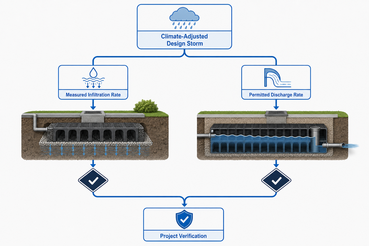
Soakaway and attenuation sizing use different primary inputs inside the same climate-adjusted design-storm framework. Soakaway sizing begins with an infiltration value measured on the site. Attenuation sizing begins with a permitted discharge rate agreed for the receiving system. Neither can be inferred from the other, yet both designs must address urban creep, exceedance routing and failure during the selected design events.
Direction one, an illustrative soakaway serving an assumed 200 m² of surface water runoff. Use an assumed infiltration rate of 1 × 10⁻⁵ m/s for this arithmetic; the actual value must come from approved site testing. The 1 × 10⁻⁶ m/s value below is a sensitivity case only, not an acceptance threshold. Assuming a project-specific 95% void ratio for illustration, a crate block 6.0 m × 2.0 m × 1.2 m gives 14.4 m³ gross and 13.7 m³ stored; a real design must use the selected module’s declared value. For the assumed geometry, perimeter 2 × (6.0 + 2.0) = 16.0 m and half depth 0.6 m give an infiltrating area of 9.6 m². Outflow is 1 × 10⁻⁵ m/s × 9.6 m² = 9.6 × 10⁻⁵ m³/s, which is 0.096 l/s. Half of 13.7 m³ is 6.85 m³, so the half-drain time is 6.85 ÷ 0.000096 = 71,400 seconds, or 19.8 hours. The 24-hour criterion cited above is a local criterion; the 19.8-hour and 198-hour results apply only to the assumed geometry, and no universal infiltration cutoff follows from them. At 1 × 10⁻⁶ m/s, the same assumed block would take about 198 hours.
Direction two, an attenuation tank serving 0.50 ha of impermeable area. England’s national standards set the permitted rate as the greater of the 50% annual exceedance probability greenfield rate or 3 l/s per hectare, so the floor here is 0.50 × 3 = 1.5 l/s. Over a 60-minute critical duration the tank can release 1.5 l/s × 3,600 s = 5,400 litres, or 5.4 m³. If the design event puts 20 mm onto the impermeable area, inflow is 5,000 m² × 0.020 m = 100 m³. Storage is therefore 100 − 5.4 = 94.6 m³. Using the illustrative 95% void ratio from direction one, the required gross crate volume is about 100 m³. Substitute the selected module’s declared void ratio before procurement.
Climate change is applied to the rainfall side of direction two, and this is where a single national percentage is misleading. Environment Agency guidance uses a management-catchment map, with central and upper-end peak rainfall allowances for 1% and 3.3% annual exceedance probability events across the 2050s and 2070s epochs. Treating “40%” as a national rule is therefore unsafe; use the value and scenario shown for the site’s management catchment. For additional context, see the related soakaway sizing page and attenuation sizing page; use the project calculations and have a drainage engineer confirm them.
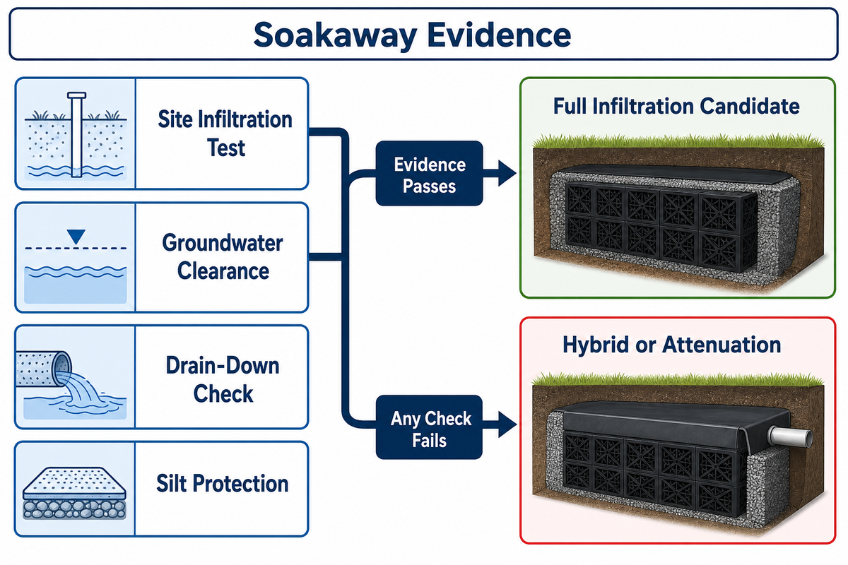
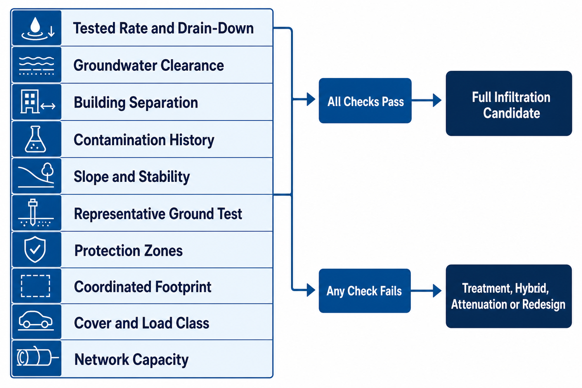
This is an editorial pre-design checklist, not a statutory test; it lists evidence to obtain and a possible next action. One failed check can rule out full infiltration or require treatment, a hybrid design, attenuation, another destination or redesign. The resulting drainage strategy follows combined hydraulic, environmental, legal and maintenance evidence rather than a product preference.
#
Condition class and threshold, or pre-design check
Evidence
If it fails: possible next action
1
Tested rate and calculated drain-down meet project acceptance criteria
Site test and calculation
Review route with designer and approving authority
2
At least 1 m between the base and the highest groundwater level
Monitoring well readings, winter period
Attenuation, hybrid design or a raised invert
3
Confirm locally accepted building and boundary separation
Coordinated site layout
Review layout with designer and approving authority
4
No known history of land contamination
Phase 1 desk study
Avoid infiltration where it could mobilise contaminants
5
Slope and stability reviewed
Geotechnical appraisal
Where the appraisal identifies seepage-related instability risk, review a non-infiltrating route
6
Site test represents proposed formation-depth ground
Trial-pit and test records
Test at actual depth and review
7
Source-protection-zone and designated-site constraints checked
Environment Agency mapping and advice
Use another approved route or obtain any required consent
8
Required footprint and clearances fit coordinated layout
Site layout
Compare other approved layouts including attenuation
9
Cover depth suits the load class over the crates
Structural build-up drawing
Change build-up or relocate
10
Downstream network has capacity for the overflow or controlled discharge
Sewerage undertaker or authority response
Agree a lower rate or another destination
Check 2 can carry programme risk. Unda, a drainage consultancy, describes a winter monitoring window running from about November to May and says that some local planning evidence requests can extend monitoring to a full annual cycle. Treat both points as a consultancy account of project practice, not a council statement or national rule, and confirm the required monitoring period with the local approving authority. Missing the required observation window can delay evidence collection, so schedule it before the geocellular crates are quoted. See the related BRE Digest 365 percolation guide and site-screening guide; the drainage designer and approving authority retain the design decision.
Site infiltration testing is performed at the proposed location and depth under a locally accepted method, and the approved result controls design. The drainage designer should keep surface-water infiltration evidence separate from foul-drainage evidence.
The Project Kit Split: what changes on the bill of materials
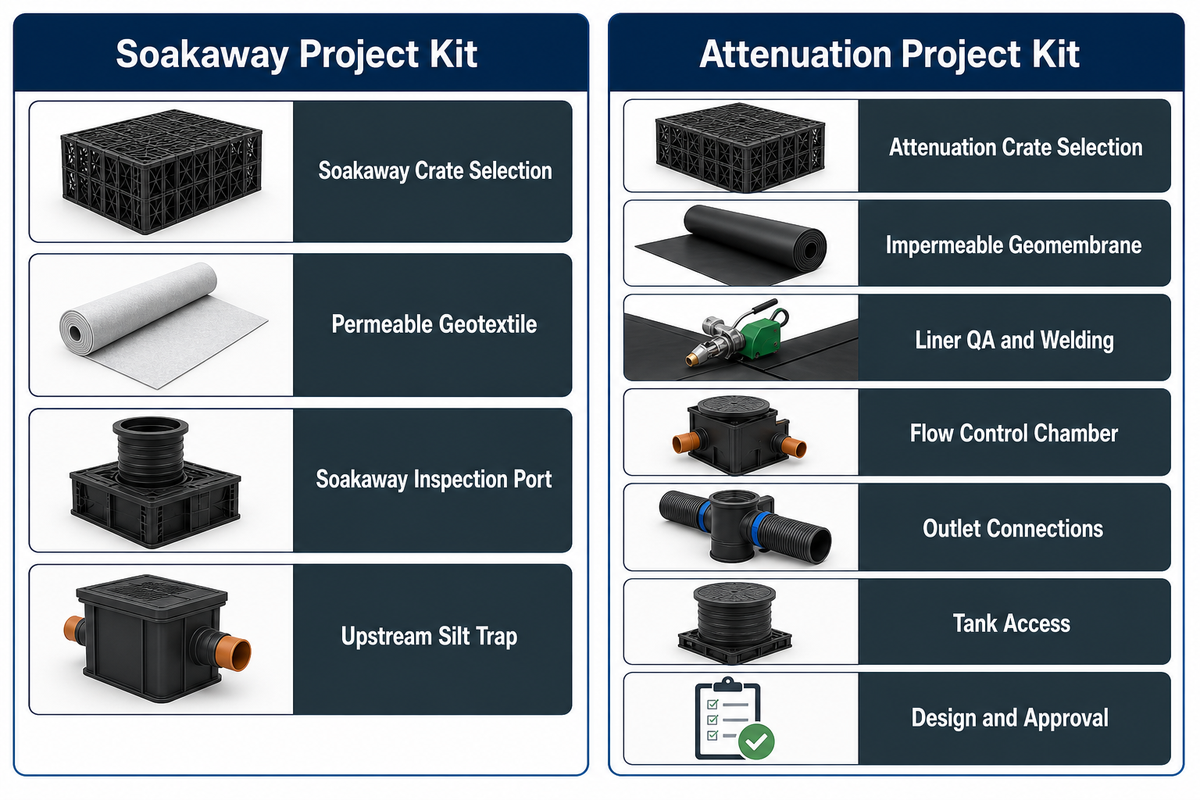
Procurement is where the choice between attenuation tanks and soakaway tanks becomes concrete. Storm Manage supplies project configurations for both soakaways and attenuation systems; exact crate model, load class, wrap and accessories are project-specific. The tanks must still be checked against their project load case, and divergence starts at the wrap before continuing through the remaining project-specific line items.
Wrap: permeable geotextile for infiltration; an impermeable liner system and its project-specified quality-assurance steps for storage.
Flow control means an orifice plate or vortex unit, plus the chamber it sits in and its connections.
Inspection provision: typical inspection provisions to confirm include a port over the crates for a soakaway and access to the control chamber and inlet catchpit for a tank; the project maintenance plan controls the final access arrangement.
Ask the drainage designer whether upstream pretreatment (e.g. a silt trap or catchpit) is required and how it is sized and maintained.
Design and approval effort: for a tank, an agreed discharge rate and hydraulic calculations; for a soakaway, a site-test result and any required monitoring record.
Compare quotations by the included membrane, welding, chamber and connections; this comparison alone does not establish correctness or price. Accessories sharing a container reduce crate space; actual yield depends on the packing plan. Storm Manage states a standard lead time of 15 to 30 days after order confirmation and up to 330 m³ of installed storage volume in a 40HQ under its best stacking arrangement; both figures are supplier information for planning purposes, not verified industry benchmarks. See the related project-cost page.
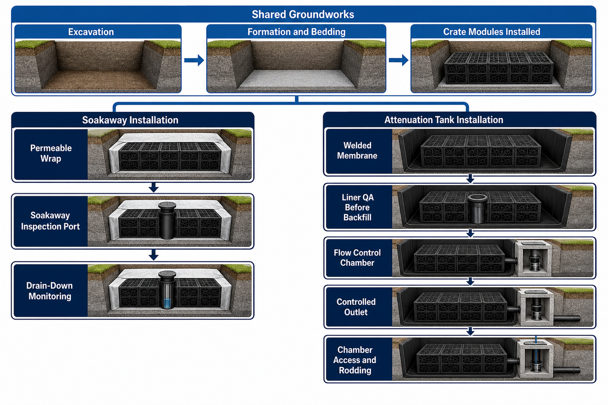
The following is a typical sequence only; approved product instructions and project method statements control the works. Installing an attenuation tank and building a soakaway share excavation, formation, bedding and load-class considerations, but the approved sequence is project-specific. How the crates are wrapped follows the approved system design. Either system may be designed beneath traffic only where the selected module, cover build-up and project load case permit. A lined attenuation build may also require welding, liner quality assurance, chamber setting and an outlet connection.
Complete the liner quality-assurance steps required by the approved product instructions and project method statement. Inlet and outlet levels, chamber preparation, backfill timing and access arrangements follow the approved project design.
Maintenance then splits along the same seam. Keep the control orifice and catchpit clear; blockage can contribute to surcharge or uncontrolled bypass where the design includes one. For a soakaway, monitor drain-down time through the inspection provision; a lengthening drain-down is an indicator to review the system condition. Confirm inspection and rodding access in the project maintenance plan; recovery options for a silted crate field depend on the installed access arrangement. See the related soakaway crate installation guide.
Destination is a consented design parameter rather than a groundworks preference. Cost alone does not justify infiltration; the proposed discharge point needs supporting evidence, such as an accepted test result or agreed rate, before crates are specified. Planning authorities assess the risk of flooding created downstream, not the merits of the product. That makes the ten checks above a programme item rather than a formality.
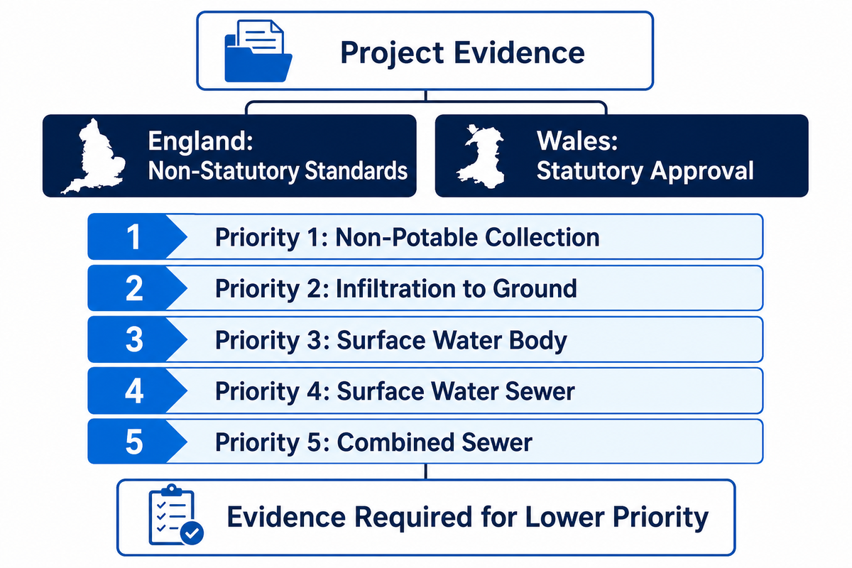
Two regimes sit behind it, and they are not the same. In Wales, the Sustainable Drainage (Approval and Adoption) (Wales) Order 2018 has been in force since 7 January 2019 under the Flood and Water Management Act 2010. Its approval requirement applies to construction work with drainage implications covering 100 square metres or more. Separately, when a developer submits a request to adopt a drainage system, the approving body has eight weeks from the first working day after receipt to determine it, unless the body and developer agree an extended period. In England, the equivalent Schedule 3 provisions of the same Flood and Water Management Act 2010 have not been commenced; instead Defra published non-statutory National Standards for sustainable drainage systems in June 2025, updated in July 2025, which local planning authorities apply through the planning system.
Those English standards also correct an assumption worth stating plainly. The discharge hierarchy does not put infiltration first: priority 1 is collection for non-potable use, priority 2 is infiltration to ground, priority 3 is an above-ground surface water body, priority 4 is a surface water sewer, and priority 5 is a combined sewer. Appropriate evidence is required to use a lower-priority destination. Rainwater harvesting therefore sits above a soakaway in the order, not beside it. That same document expects systems to half empty their runoff volume within a maximum of 24 hours.
A dated public signal is investment and implementation, not a product-market forecast. The UK Parliament’s 2026 Flood resilience in England: Government Response states that at least £10.5 billion will be invested in flood and coastal resilience up to 2036 and commits to increasing the quantity, quality, adoption and maintenance of sustainable drainage systems in England. That does not prove growth in attenuation-tank sales; it explains why evidence, adoption and maintainability are receiving more scrutiny as urban development adds pressure to drainage infrastructure. Rainwater harvesting systems, infiltration and controlled storage may all form part of a stormwater system that works across the whole site. Tanks may provide one component, but managing stormwater still depends on the destination, treatment train, maintenance ownership and exceedance route. See the related CIRIA compliance guide for attenuation tanks. CIRIA’s C737 publication page states that C737 supersedes C680 and that structural designs should now be based on C737. Anyone building stormwater management systems around the earlier document should confirm which guidance their designer has used.
Yes in England, subject to site evidence and local approval; infiltration sits at priority 2 in England’s 2025 national standards. In Wales, confirm the proposal against the local sustainable drainage approving body’s requirements.
What has changed is the evidence needed. Infiltration ranks below collection for non-potable use and above discharge to a watercourse or sewer, and using a lower-priority destination requires evidence. A soakaway must be justified with a measured infiltration rate, groundwater clearance and site screening rather than assumed. If project criteria are not met, infiltration may require redesign or another approved route; if they are met, the proposal remains subject to approval.
Q: How do I know if I need an attenuation tank or soakaway?
Site evidence and the approved drainage strategy decide. Start with infiltration and groundwater evidence; a failed project criterion may rule out full infiltration or require another approved route.
The tested infiltration rate, groundwater criterion, contamination evidence, ground conditions and available plan area inform the designer’s assessment. If those project criteria are not met, the design may need attenuation, a hybrid arrangement or another approved route. Sequence matters: commission the evidence before the drainage strategy is fixed, because the result can change the layout as well as the product configuration.
Q: Are soakaway crates and attenuation crates the same thing?
Storm Manage supplies project configurations for both systems; exact crate model, load class, wrap and accessories are project-specific and must be checked against the declared project load case.
Soakaway packages use permeable geotextile, while attenuation packages use impermeable geomembrane, welding, a flow control chamber and its connections. Check the exact project data and accessory schedule rather than relying on the product name when comparing quotations. The selected module and cover build-up still need project-specific structural verification before procurement.
Q: Can I convert a soakaway into an attenuation tank later?
Conversion is a new drainage-design exercise. The drainage designer assesses whether to expose, reuse or replace the existing storage and how the revised hydraulic, structural, liner and approval requirements will be met.
Reused storage needs liner, inlet, outlet, control and inspection detail. If future reuse is planned, include it in the initial hydraulic, structural and water-quality design rather than relying on a capped-connection conversion strategy. Existing component condition, the receiving system and the approving authority’s requirements also affect the decision.
Q: How far from a building does a soakaway have to be?
Confirm both the building offset and groundwater criterion with the approving authority before the project layout is fixed; they are separate checks that need independent confirmation.
The local-authority guidance cited here uses at least 1 m between the soakaway base and the highest recorded groundwater level. Confirm whether that criterion applies to the project, and confirm the building offset separately with the approving authority. Foundation wetting, soil type and formation depth are matters for the project design.
Q: What is the lifespan of an attenuation tank?
No universal lifespan follows from the product name. Ask for long-term strength and creep data tied to the project load case and the manufacturer’s declared design life.
Treat every design-life claim as a project-specific engineering declaration because it rests on creep behaviour: the tendency of a plastic to deform permanently over time under constant stress. BSI’s published scopes separate the questions: BS EN 17150 covers short-term compression strength, BS EN 17151 covers long-term compression strength, and BS EN 17152-1 specifies stormwater boxes made of PP and PVC-U. A short-term crushing figure in kN/m² does not establish long-term performance under permanent surcharge. Ask for the long-term test result and the depth of cover used in the design. For traffic-loaded installations, request the declared long-term strength, creep reduction factor and structural load case.
Key takeaway
Test the ground first. A tested infiltration rate or calculated drain-down that fails the project’s acceptance criteria may rule out full infiltration; so may insufficient groundwater clearance. The design may then require redesign, attenuation, a hybrid arrangement or another approved route. Size a soakaway from the measured rate and an attenuation tank from the permitted discharge rate, then buy the wrap, outlet and flow-control chamber to match. Storm Manage supplies project configurations for both soakaways and attenuation systems; exact crate model, load class, wrap and accessories are project-specific.
Storm Manage supplies geocellular crates and accessories. The discharge decision, the calculations and the approval belong to the project’s drainage designer and the approving authority.


![Stormwater Detention Tank Manufacturers [2026 Vetting Guide]](https://stormmanage.com/wp-content/uploads/2026/08/stormwater-detention-tank-manufacturers-featured-768x512.png)

![Stormwater Detention Tank Manufacturers [2026 Vetting Guide]](https://stormmanage.com/wp-content/uploads/2026/08/stormwater-detention-tank-manufacturers-featured-150x150.png)