We use the details you submit to review and respond to your project enquiry. Entries are handled in this website’s WordPress database using Fluent Forms; our hosting and email providers may process the submitted details. Other technical providers receive only the data described in our Privacy Policy.
Please do not send passwords, payment-card details, government identification numbers, sensitive personal data, or unnecessary confidential third-party information.
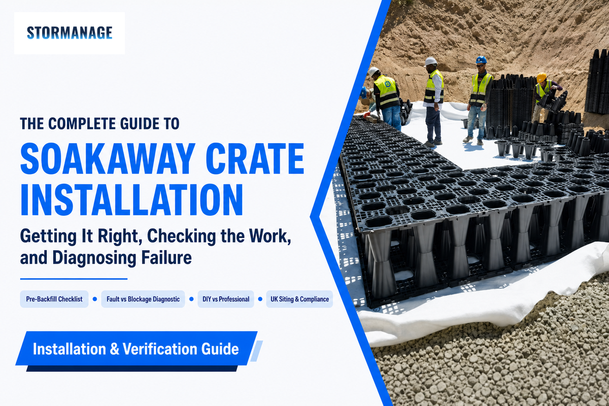
Soakaway crate installation is where most of the risk in a stormwater infiltration system actually lives, not in the crate itself. Even a correctly specified, correctly manufactured crate can fail within 5 years if it goes into the ground with the wrong backfill, a torn geotextile wrap, or the wrong siting distance, while the same product installed to spec can run for its full manufacturer-stated 50-year design life. This guide covers the full lifecycle: what the product actually is, how the percolation test constrains the design, a short recap of the physical build sequence, and then the two things almost nothing else online covers: what to check before the trench is backfilled, and how to tell an installation defect apart from routine blockage after the fact.
One quick note on where this guide fits before the detail starts: if you landed here searching how to install a soakaway UK, soakaway installation cost, or soakaway blocked how to unblock, all three are covered below, sizing and the physical build sequence first, a full domestic cost range in the DIY-vs-professional section, and a dedicated fault-versus-blockage diagnostic table further down. And if you’re weighing up installing soakaway crates yourself against fitting soakaway crates through a contractor, the soakaway crate installation instructions in the step sequence below apply either way.
What Counts as a Soakaway Crate Installation (And What Doesn’t)
A soakaway crate installation is the placement of modular, injection-moulded plastic infiltration units, wrapped in geotextile membrane and buried below a drained surface, that store rainwater runoff temporarily and let it disperse into the surrounding soil. This guide covers surface-water (stormwater) soakaway crates specifically: roof drainage, driveways, car parks and similar hard-standing runoff.
Good stormwater water management starts with the same question every time, the one local building-control percolation guidance exists specifically to answer: is this ground actually going to accept the water? Loamy or sandy soil is generally favourable for infiltration; heavy clay soil is generally not, and that single variable does more to determine whether a project succeeds than the choice of crate brand ever will.
It doesn’t cover septic tank drainage fields or boiler condensate soakaways, which are a different category of structure with different sizing rules, different contamination risks, and often a different legal siting distance from any building. Industry reference material on soakaway design is explicit that a drainage field for treated effluent and a surface-water soakaway aren’t interchangeable, and mixing up the two rulesets is a documented source of siting mistakes.
💡Pro Tip
If your search brought you here because you’re dealing with a septic system or a boiler condensate line, the design rules in this guide (5m/2.5m siting, BRE-365-based sizing) do not directly apply, those systems carry their own, generally stricter, separation distances.
Percolation Test: What It Actually Proves Before Any Crate Goes in the Ground
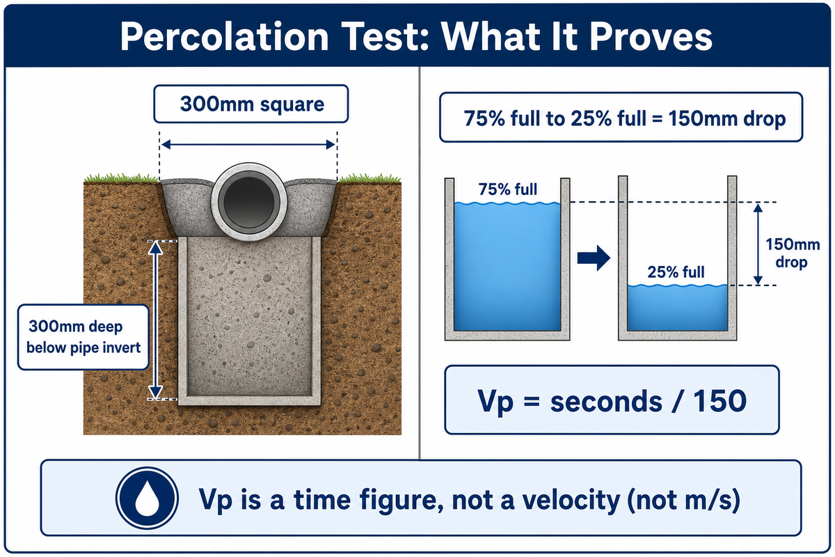
Whether the ground can accept water fast enough for a soakaway to work at all is exactly what a soil percolation test tells you, and how big the storage volume for the soakaway pit needs to be. Per Stratford-on-Avon District Council’s published building-control guidance, the standard method excavates a test hole at least 300mm square and roughly 300mm deep below the pipe invert, fills it with water, and measures the time for the level to drop from 75% full to 25% full, a 150mm drop. Divide that time (in seconds) by 150 to get Vp, the average seconds required for the water to fall 1mm.
Storm Manage’s own published lead time for this product runs 15 to 30 days from order confirmation, a figure worth having to hand when a project timeline depends on it. For small soakaways serving 25m² or less, UK design guidance allows a simplified worst-case rainfall assumption for a quick sizing check, for anything larger, the full BRE Digest 365 or the wider BS EN 752:2017 drainage-design series applies instead.
Vp itself is a time figure (seconds per mm of fall), not a velocity, so it isn’t quoted directly in m/s. What it feeds into is a separate soil infiltration-rate figure, derived from Vp using the BRE 365 method and typically expressed in m/s: broadly, the faster water infiltrates (the higher that rate), the more workable a soakaway is, and ground that drains too slowly needs an alternative disposal route instead (attenuation with a controlled outlet, or a sewer connection) rather than a soakaway. Separately, a related, independent UK drainage reference makes a practical point worth carrying into your own project planning: running the full formal percolation calculation is “not always feasible or necessary” for a quick go/no-go decision, a simpler trial pit, left overnight, is often enough to establish whether infiltration is realistic before you commit to the full test.
How Many Crates Does a Typical Installation Need?
There’s no fixed crate count independent of your site: the number is a function of your percolation result and your contributing drained area, not a lookup table. A practical rule used across UK guidance is to size storage volume from the drained roof or hard-standing area, the local design rainfall rate, and the measured infiltration rate together, then convert that volume into crate units for your specific product range.
Module dimensions vary by manufacturer. One published worked example, using a separate 50mm/hr design-rainfall assumption from a different reference than the simplified UK sizing assumption above (worked examples like this vary by source and storm-return-period basis, so treat the two as independent reference points rather than the same number), illustrates the underlying logic using that source’s own formula, Volume = Area x (rainfall rate / 3000), a shortcut method whose divisor bundles in that source’s runoff and duration assumptions rather than being a plain mm-to-m unit conversion: a 60m² drained area at that 50mm/hr assumption works out to roughly 1m³ of required storage (60 x (50/3000) = 1) by that method, before any adjustment for the specific crate module’s void ratio. Treat any generic “X crates per Y m² of roof” figure you see elsewhere as a rough starting point only, not a substitute for running your own numbers against your actual percolation result, which is exactly what Storm Manage’s installation page and its built-in sizing calculator are there to help with.
Where the site percolation test result is genuinely borderline, or the ground is a mix of clay lenses over more permeable strata, that’s a case for a project-specific sizing conversation with your supplier rather than a self-service calculation, the margin for error narrows considerably. As a rough planning reference, a typical domestic module measures around 1000mm × 500mm × 500mm, so even a modest 1m³ requirement translates into a handful of interlocked units, not a single oversized box.
Installation Sequence at a Glance
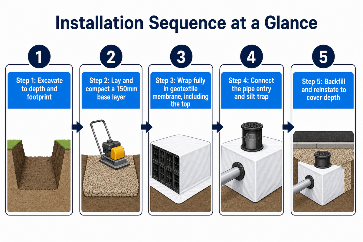
Installing a soakaway follows the same broad sequence whether you’re building a small domestic soakaway system or a larger plastic soakaway crates installation for a commercial site: excavate to the depth set by your percolation test and design, lay a compacted base layer, place and interlock the crates, wrap the assembly fully in geotextile membrane, connect the inlet and outlet pipework, then backfill and reinstate the surface. A modern soakaway crate system stores far more water storage volume per cubic metre of excavation than an old-style rubble pit, which is exactly why getting each step right matters more, not less. A published Tricel Stormwater case study (Killarney, Ireland, July 2024, 120m³ system serving a 12–13 house development plus car park) followed the same three-phase pattern: excavate and prepare a compacted base, install a geotextile/membrane/geotextile “sandwich” and assemble the crates within it, then backfill.
The five-step sequence for installing soakaway crates, at a glance:
Excavate to the depth and footprint set by your percolation test and load-class requirement, ready for the soakaway crates and their connecting drainage pipe run.
Lay and compact a base layer — typically a 150mm layer of sharp sand or pea shingle — so the assembled crates sit on a level, stable footing rather than directly on disturbed soil.
Lower the crates into position and secure the crates with the connectors or cable ties supplied, building the soakaway crate system module by module; wrap the completed membrane and crate wall fully in non-woven geotextile membrane, including the top of the crates, so no exposed panel is left unprotected.
Cut and connect the pipe entry / entry point for the incoming stormwater pipe, plus any silt trap or removable bucket for inspection access, so the finished crate system has a clear route for water to drain in before backfill closes it off.
Backfill around the sides (side fill) with sharp sand or pea gravel, then reinstate the surface to the required cover depth.
The number of crates and the overall size of soakaway you end up building both trace back to the sizing step covered above, there’s no shortcut that skips the size of your soakaway calculation and goes straight to a generic module count. Storm Manage’s crate range is manufactured to a stated 95% void ratio; a traditional rubble-filled pit typically runs well below that (commonly cited industry rule of thumb, not independently lab-verified in this round), meaning noticeably more usable storage per cubic metre excavated when the crate system is installed correctly, the qualifier “correctly” is doing real work in that sentence, which is exactly why the next two sections exist.
This is deliberately a summary, not a full how-to: Storm Manage publishes a detailed, layer-by-layer installation and design walkthrough with drawings and sizing tools for exactly this step, and repeating that depth here would just duplicate it. If you’re at the execution stage, Storm Manage’s own step-by-step installation and design walkthrough is the more useful next stop, this guide picks up from where that one leaves off.
The Pre-Backfill Verification Checklist
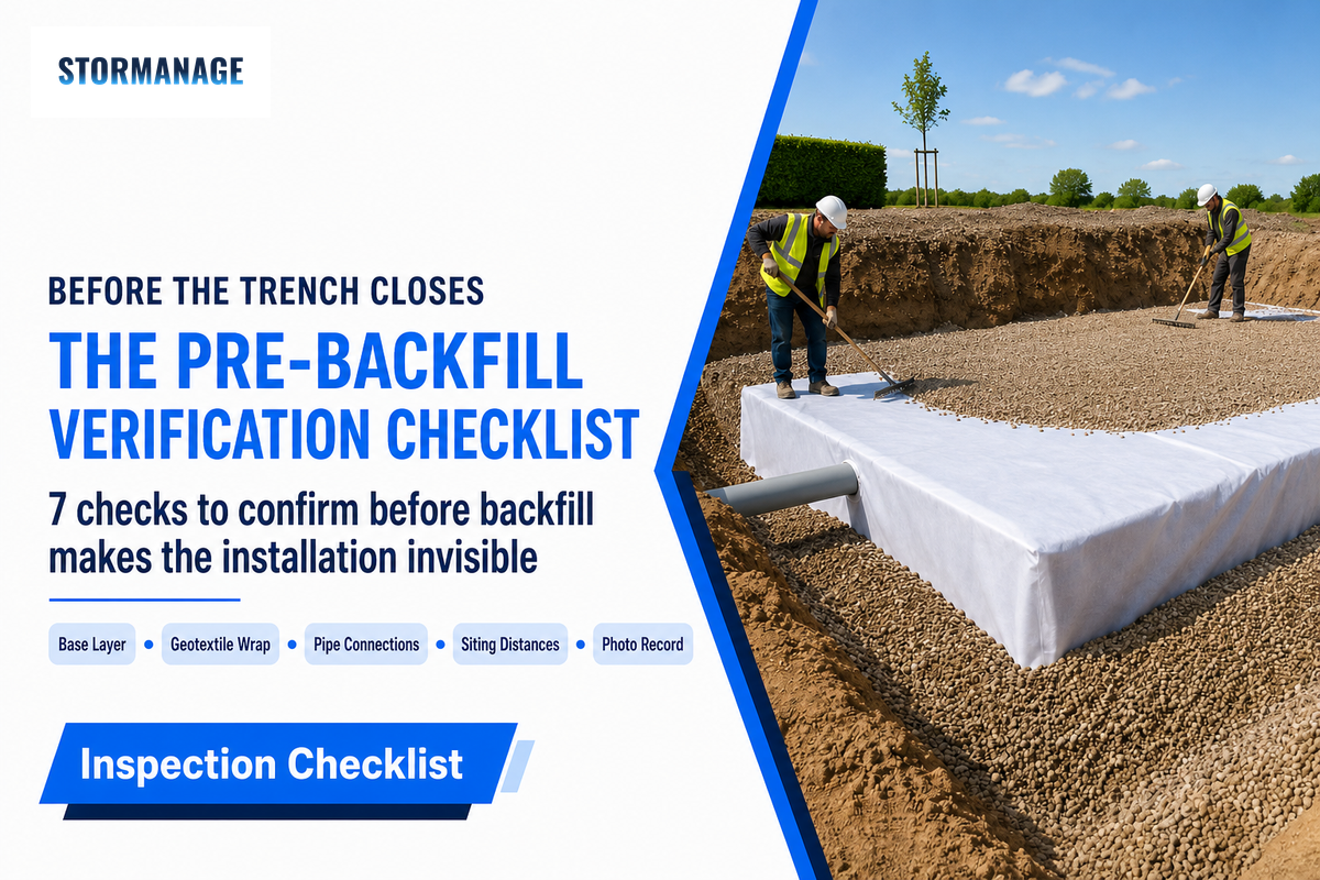
Once backfill goes in, almost everything about the installation becomes invisible. Torn geotextile corners, missing clips, an undersized base layer, none of it shows up again until the system starts underperforming, sometimes years later. That makes the pre-backfill stage the single most valuable inspection point in the entire project, and it’s the one step that almost no installation guide, manufacturer or independent, treats as a discrete checklist in its own right.
The Pre-Backfill Verification Checklist
✔ Base layer is compacted evenly, with no visible soft spots or standing water in the excavation.
✔ Crate modules are correctly interlocked/clipped, with no visible gaps between units.
✔ Geotextile membrane fully encloses the assembly on all sides, including the base — not just the top and sides.
✔ Membrane overlaps and joins are secured (taped or tied per the wrap manufacturer’s method), with no visible tears from handling.
✔ Inlet and outlet pipe connections are seated, aligned to design invert levels, and free of debris.
✔ Measured siting distances (from buildings and boundaries) match the design drawing, not just the original plan.
✔ Photographs taken of the wrapped assembly before backfill begins, dated and kept with the project file.
This list reflects a pattern the supplier side sees repeatedly: the most common, least visible cause of underperformance is an incomplete or damaged geotextile wrap at exactly this stage, not a defect in the crate itself. It’s also why the wider industry direction is toward building inspection access directly into the product rather than leaving verification to chance, and it lines up with the emphasis the UK’s national SuDS standards place on infiltration systems actually functioning as designed, not just being built to a drawing.
If you’re commissioning the work rather than doing it yourself, ask the installer for these photographs as a deliverable, not an afterthought, it costs nothing at the time and is the only record you’ll have once the ground is closed.
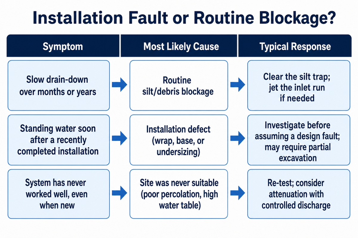
Installation Fault or Routine Blockage: A Diagnostic Table
Three genuinely different reasons can stop a soakaway draining properly, and each one calls for a different response. Confusing them wastes money: excavating and rebuilding a system that just needs its silt trap cleared, or repeatedly jetting a system that was never sited on suitable ground to begin with.
Soakaway underperformance has at least three distinct root causes — this table routes symptoms to the most likely one.
What you’re seeing
Most likely cause
What confirms it
Typical response
Limitations / not suitable for
Slow drain-down that developed gradually over months or years
Routine silt/debris blockage
Silt trap or inlet pipe visibly clogged on inspection
Clear the silt trap; jet the inlet run if needed
Not applicable if the wrap itself has failed — clearing the trap won’t fix a torn membrane
Standing water appeared soon after a recently completed installation
Installation defect (wrap, base, or undersizing)
No pre-backfill verification records exist; excavation (if undertaken) shows soil migration into the void space
Investigate before assuming a design fault; may require partial excavation
Cannot be confirmed without either verification photos or physical inspection — don’t guess
System has never worked well, even when new
Site was never suitable (poor percolation, high water table)
Percolation test result was marginal or absent at design stage
Re-test; consider attenuation with controlled discharge instead of infiltration
No installation fix resolves ground that genuinely can’t infiltrate at the required rate
Sudden loss of performance after nearby groundworks or heavy plant traffic
Physical damage or compaction from external works
Timeline correlates with known nearby construction activity
Localised inspection near the affected area
Distinguish from load-class-related settlement, which is a separate, gradual pattern
Performance drops only in winter or after heavy rain, typically for 2 to 3 months, then recovers
Seasonally high water table reducing the ground’s effective infiltration capacity
Correlates with wet-season timing; a dry-season retest shows normal function
No fix needed if it self-resolves seasonally; consider attenuation if it doesn’t
Distinguish from a permanent siting fault — seasonal variation is expected on some ground, not a defect
Gradual capacity decline after more than 10 years of otherwise normal service
Natural long-term silt and biofilm buildup within the expected service life
Age is consistent with the original design life; decline is gradual, not sudden
Schedule routine desilting rather than assuming a fault
Not applicable to a system still well within its first 5 years showing the same symptom
Sudden total blockage appearing after nearby tree or hedge growth
Root ingress through a damaged or unsealed pipe joint
Visible root intrusion at the inspection point on excavation
Cut back the roots, reseal the joint, and consider a root barrier for the future
Won’t recur from this cause alone once the joint is properly resealed
Several nearby soakaways underperforming at the same time
Shared groundwater saturation from cumulative loading across multiple systems
More than one system in the same area affected simultaneously, not just yours
May need additional capacity or an alternative disposal route, not a single-unit repair
A design-capacity issue across the site, not a fault in any one installation
Standing water directly above the crate footprint only, typically within 1 to 2m of the edge, not the wider garden
Settled or compacted cover material reducing the infiltration path at that spot
A localised depression sits exactly over the buried crate zone on inspection
Check and reinstate the cover material rather than assuming the crate has failed
Distinguish from a wider drainage problem affecting the whole area
Is a Blocked Soakaway the Same as a Failed Installation?
No, and treating them as the same thing is the most common mistake in this diagnosis. By definition, a blocked soakaway is a maintenance event: silt, debris or root ingress has restricted flow into an otherwise sound system, and the standard fix is clearing the silt trap or jetting the inlet pipework. A failed installation is a structural or execution problem instead: a compromised wrap, inadequate compaction, or ground that was never suitable to begin with.
That last cause traces back to whether the site was ever properly tested against the standard percolation-test procedure in the first place, not a maintenance issue at all.
Independent UK drainage guidance treats this distinction as routine: an older soakaway that has stopped functioning is described as usually blocked with silt and mud, remediable in many cases by removing the fill and accumulated silt to rejuvenate the system, without needing a full rebuild. As noted above, the diagnostic table is a starting point for narrowing which category you’re actually in, not a substitute for a physical inspection when the cause isn’t obvious from the symptoms alone.
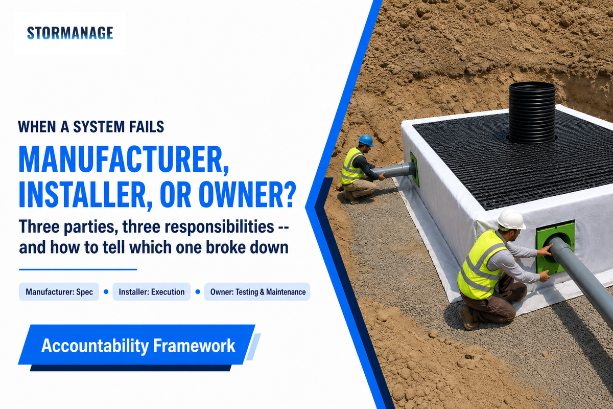
Who’s Accountable When It Fails: Manufacturer, Installer, or Owner
Most soakaway crate manufacturers, Storm Manage included, are explicit that their role stops at the product: engineering the crate, connector and wrap system to a stated specification, and providing installation drawings, not carrying out the physical, on-site build. In Storm Manage’s own words: “we don’t carry out on-site soakaways installations; our responsibility is to engineer the system and support the installation team.” That’s a reasonable division of labour, but it means the accountability question has three distinct parties, not one.
Product specification (void ratio, load class, material composition, and crate geometry that can itself be patented engineering, as with the Otto Graf percolation-block patent family) and accurate installation guidance sit with the manufacturer. The installer (whether a contractor or a competent DIYer) is responsible for executing that guidance correctly: compaction, wrap integrity, siting distance, connections. The owner or project developer is responsible for commissioning a percolation test and appropriate design before ordering, and for reasonable maintenance afterward. When a system fails, working out which of the three broke down is exactly what the pre-backfill verification records (see above) and the diagnostic table exist to support, without them, it becomes a much harder argument to have.
“Nine times out of ten, a failed crate soakaway didn’t fail because of the crate; it failed because the geotextile wrap was incomplete or the compaction was rushed at Layer 2. We tell every distributor the same thing: follow the layer sequence exactly, because the crate is only as good as what’s around it.”
— Senior Application Engineer, Storm Manage
One further point worth flagging honestly: some suppliers, including Storm Manage’s own published material, note that industry structural-design guidance for geocellular systems has moved from an older reference (CIRIA C680) to a newer one (CIRIA C737). We haven’t independently verified the supersession against a second source this round, so treat it as Storm Manage’s stated position rather than an independently confirmed fact when it matters to a compliance submission, check directly with CIRIA or your structural engineer for a project that depends on it.
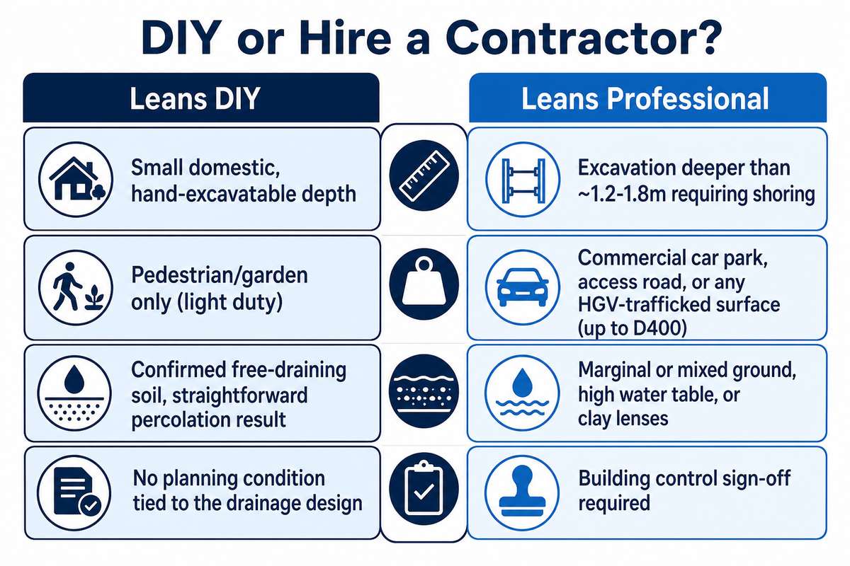
DIY or Hire a Contractor: A Threshold Table
On suitable ground, with a straightforward percolation result, a small domestic soakaway is within reach of a competent DIYer with two people and a weekend. Larger, commercial, or trafficked installations are a different proposition, not because the crate assembly itself is complex, but because the consequences of a mistake scale with the site.
DIY-vs-professional threshold for a soakaway crate installation, by project scale and load class.
Factor
Leans DIY
Leans professional
System size
Small domestic, single-property, hand-excavatable depth
Commercial/multi-unit, or excavation deeper than ~1.2–1.8m requiring shoring
Load class
Pedestrian/garden only (light duty)
Commercial car park, access road, or any HGV-trafficked surface (heavier duty class, up to D400)
Ground conditions
Confirmed free-draining soil, straightforward percolation result
Marginal or mixed ground, high water table, or clay lenses
Regulatory exposure
No planning condition tied to the drainage design
Building control sign-off or planning condition requires documented compliance
Cost is a secondary factor to the table above, not the primary one, but it does move with scale: Storm Manage’s own published guidance cites local UK trade and installer-forum estimates of roughly £1,500 to £2,500 (installed) for a typical domestic crate soakaway, covering both labour and materials, while a commercial installation is priced per project against the specific volume and access constraints. If you land on “professional,” sizing and kit selection for the specific product range is a separate decision from the execution question this guide focuses on: sizing and kit selection guidance and a six-check evidence framework for choosing a kit before you order cover that ground.
Legal Siting Rules and Building Regulations Compliance
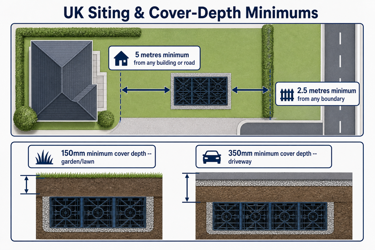
UK building-control guidance, administered by local authorities, is consistent on the core siting minimums for a standard surface-water soakaway: at least 5 metres away from any building or road (5m), and 2.5 metres (2.5m) from any boundary, with additional restrictions where the site is in an area of unstable land, near the water table, or close enough to another soakaway or drainage field that the ground’s overall soakage capacity would be exceeded. These aren’t guidelines, a soakaway sited too close to a building, or not sufficiently away from the building it’s meant to protect, can be required to be repositioned. Cover depth follows a similar application-based rule: 150mm minimum for garden or lawn use, rising to 350mm for light traffic such as a domestic driveway.
Where a system carries a higher load class (D400-rated, for trafficked surfaces), the siting and cover-depth requirements interact with the structural design in ways that a nominal rating alone doesn’t resolve. Shallow and deep installations under the same nominal load class can be governed by different transient, permanent and lateral loading conditions, so a single “D400 means X depth” rule of thumb isn’t reliable, and a duty label by itself doesn’t confirm suitability for a specific buried application without checking it against the actual cover depth, pavement construction and construction traffic expected on site.
Siting minimums (regulatory) and typical cover depths (manufacturer/industry guidance) for a standard UK surface-water soakaway crate installation.
Requirement
Minimum
Basis
Distance from any building or road
5 metres
Regulatory (local building control)
Distance from any property boundary
2.5 metres
Regulatory (local building control)
Cover depth — garden/lawn, pedestrian only
150mm minimum
Manufacturer/industry guidance, not a statutory figure
Cover depth — driveway, light vehicle traffic
350mm minimum
Manufacturer/industry guidance, not a statutory figure
Load class selection should be made independently of cover depth, the two are related but not interchangeable decisions, and mistakenly combining them is a frequent error. For quick reference, the table below maps common real-world application scenarios to the load-class family each typically falls under:
Load class by application scenario for a soakaway crate installation, nine common site types mapped to the EN 124 class that applies to each.
Application scenario
Load class
Verification needed
Garden bed, flower bed, soft landscaping
EN 124 A15
Standard cover depth check only
Lawn, pedestrian-only garden path
EN 124 A15
Standard cover depth check only
Single-property domestic driveway (car only)
EN 124 B125
Confirm cover depth against vehicle weight
Shared driveway (occasional van or light truck)
EN 124 B125
Confirm against heaviest regular vehicle, not just cars
Small private car park (cars only, no HGV/delivery access)
EN 124 B125
Confirm no commercial or delivery vehicles use the same surface
Retail or commercial car park (mixed traffic)
EN 124 D400
Structural review required
Commercial access road / loading bay
EN 124 D400
Engineer-verified cover depth required
Bus route or regularly HGV-trafficked estate road
EN 124 D400 (engineer-verified)
Full structural review, not a nominal-label check
Public highway or arterial road
EN 124 D400 (engineer-verified)
Full structural review, not a nominal-label check
Worth being precise about scope here: these EN 124 classes rate the surface-level covers, gratings and access points sitting above the installation, the standard that applies to anything a wheel or foot actually contacts, not the buried crate structure itself, which carries its own separate compressive/structural rating from the crate manufacturer and needs checking against that spec independently. Note that the same D400 label appears across the last four rows, yet the cover depth, backfill specification and construction-traffic tolerance a structural engineer would sign off on can differ meaningfully between a retail car park and a public highway. That’s the practical meaning of the “duty label alone doesn’t confirm suitability” point above, the class name is a starting point for the conversation with your engineer, not the end of it. Storm Manage’s heavy-duty soakaway D400 guide goes into D400 specification in more depth than this section can.
For a system that’s already in the ground, where you’re checking retroactively rather than planning a new installation, the practical version of this compliance check is simpler than it sounds: pull the original design drawing (or the pre-backfill verification photos, if you have them) and measure the as-built distances against the table above, rather than assuming the original plan was followed exactly on site. This is the retrofit angle most siting-rule content skips, because it’s written for people planning a new installation, not auditing one that already exists.
What’s Changing in 2025-2026: The England SuDS Standards Update and What It Means for Installations
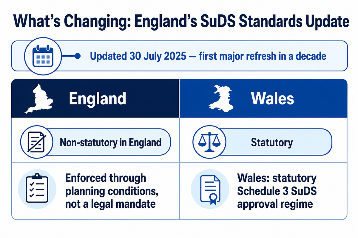
England’s National Standards for Sustainable Drainage Systems were updated on 30 July 2025, the first major refresh in a decade. It’s worth being precise about what that update does and doesn’t do: per industry drainage-sector commentary, it remains non-statutory in England, meaning compliance is enforced through planning conditions rather than a direct legal mandate.
It applies specifically to England, Wales operates under a separate, statutory Schedule 3 SuDS approval regime that isn’t the same framework. Treating this as one uniform “UK requirement” is a real, common imprecision worth avoiding, since the practical compliance path genuinely differs by nation.
For a soakaway crate project specifically, the update’s most direct relevance is at the planning-approval stage administered day-to-day by local authorities, the same kind of local building-control office that signs off on the percolation testing and siting this guide covers, where the update reinforces infiltration and source-control drainage as the preferred approach over piping water straight to sewer. We haven’t found clear evidence in this round that the update extends new retrospective compliance obligations onto already-completed installations, if you’re checking an existing system rather than planning a new one, the siting and design rules in the sections above remain the operative reference, not the 2025 update specifically.
Getting the England/Wales distinction wrong carries a real risk for a live project: citing the wrong regime in a planning submission, England’s non-statutory update instead of Wales’s statutory Schedule 3 process, or vice versa, risks the submission being sent back for correction and resubmission, adding avoidable time to the planning timeline for no reason other than citing the wrong document.
Frequently Asked Questions
Q: What is an inspection chamber, and do I need one?
An inspection chamber is an accessible cover point built into or adjacent to a soakaway that lets you check for silt build-up and blockages without excavating the whole system.
For domestic systems built from rectangular chamber sections, an inspection chamber is often part of the standard component set. For crate-based systems, equivalent access is typically provided at the inlet/silt-trap point rather than into the crate void itself, since the crate assembly is fully wrapped and buried. If your design doesn’t have an obvious access point, that’s worth raising with your supplier before backfill, it’s much cheaper to add at that stage than to retrofit later.
Q: Foul water drainage vs surface water drainage: what’s the difference?
Foul water is wastewater from toilets, sinks and appliances, which must go to a sewer or treatment system; surface water is rainwater runoff from roofs and hard-standing, which can often go to a soakaway.
UK Building Regulations treat these as separate systems with separate rules, and connecting them incorrectly (for example, routing surface water into a foul sewer) can breach both regulations and, in some areas, incur additional charges. A soakaway crate installation is specifically a surface-water solution; if you’re unsure which category your runoff falls into, that’s a question for your local building control team before design, not after installation.
Q: How can you tell if a soakaway installation has failed?
Standing water that appears soon after a new installation, with no pre-backfill verification records to check against, is the strongest early signal of an installation defect rather than routine blockage.
Use the diagnostic table earlier in this guide to work through the distinction systematically: routine blockage develops gradually over time and responds to clearing the silt trap; an installation defect tends to show up relatively early and won’t be resolved by maintenance alone. If you genuinely can’t tell from symptoms, a physical inspection (or partial excavation, for a serious case) is the only way to confirm the cause rather than guess.
Q: What should I do if a newly installed soakaway isn’t draining?
First check the inlet pipe and silt trap for an obvious blockage, then review whether a percolation test was carried out at all before the original installation.
One that never worked, even when new, most often points to a design-stage issue, a percolation test that was skipped, marginal, or not representative of the actual ground conditions, rather than a workmanship problem. If the inlet and silt trap are clear and the system still isn’t draining, that’s a stronger signal to re-test the ground than to assume the crates themselves are at fault.
Q: Can a badly installed soakaway be repaired without full excavation?
Sometimes, a silted-up system can often be rejuvenated by removing fill and accumulated silt, but a torn or missing geotextile wrap generally requires re-excavation to fix properly.
The remediation path depends heavily on which failure mode you’re dealing with. Silt and debris blockage is the more forgiving case: independent UK drainage reference material describes removing the fill material and accumulated silt from a chambered soakaway as a workable way to rejuvenate it without a full rebuild, and the same logic applies to a silted crate system’s inlet and silt trap. A compromised geotextile membrane is a different problem entirely, there’s no practical way to re-wrap a buried crate assembly without exposing it, which is exactly why the pre-backfill verification step earlier in this guide matters as much as it does. If you’re weighing up whether a partial dig is worth attempting versus a full rebuild, that decision usually comes down to how localised the suspected damage is and how old the installation is relative to its design life.
Q: Does a poor installation void the crate manufacturer’s warranty?
Typically yes for defects traceable to installation rather than the product, which is why manufacturers who don’t carry out the physical build are explicit about that division of responsibility upfront.
This is exactly the accountability question covered earlier in this guide: manufacturer warranties generally cover the product meeting its stated specification, not workmanship carried out by a separate installer or DIY builder. Keeping the pre-backfill verification records is the practical way to establish, after the fact, whether a failure traces back to the product or the execution.
Q: How long does a professional soakaway crate installation take?
A small domestic system is typically a single day for two workers once excavation is ready, though shoring, access constraints, or poor weather can extend that.
Excavation and shoring, not the crate assembly, usually set the real timeline.
About This Analysis
This guide was compiled from UK local-authority building-control guidance, independent drainage-industry reference material, published trade-press commentary, and Storm Manage’s own field experience with geocellular crate installations across 1,000+ projects in 30+ countries since 2014. Per Storm Manage’s own account of its operations (not independently audited by us): production runs through its Shenzhen facility, stated as 8 injection-moulding machines across roughly 8,000m² of factory floor, producing around 5,000m³ of crate modules a month, with the flat-packed crates from one standard 40-foot high-cube export container said to build out to as much as 330m³ of assembled, installed storage volume on site. Where a claim rests on a single source rather than independent verification, we’ve said so directly rather than presenting it as settled fact.




![Stormwater Detention Tank Manufacturers [2026 Vetting Guide]](https://stormmanage.com/wp-content/uploads/2026/08/stormwater-detention-tank-manufacturers-featured-768x512.png)




![Stormwater Detention Tank Manufacturers [2026 Vetting Guide]](https://stormmanage.com/wp-content/uploads/2026/08/stormwater-detention-tank-manufacturers-featured-150x150.png)