We use the details you submit to review and respond to your project enquiry. Entries are handled in this website’s WordPress database using Fluent Forms; our hosting and email providers may process the submitted details. Other technical providers receive only the data described in our Privacy Policy.
Please do not send passwords, payment-card details, government identification numbers, sensitive personal data, or unnecessary confidential third-party information.
Offline Attenuation Tank: 5 Checks vs Online Storage
Updated October 2026
An offline attenuation tank sits off the main drainage route and is supplied with water through diversion during large events. Online stores are situated on the principal flow path. That distinction changes how the system fills, how combined discharge is checked and what remains accessible for inspection.
The label alone doesn’t prove that an ‘attenuation system’ will work. A design still needs a hydraulic model, surveyed levels, an agreed receiving-system boundary and a maintainable construction package. The five checks below help an engineer, contractor or procurement team expose those inputs before a quote becomes an order.
Direct answer
Choose offline storage only after tracing normal flow, peak filling and drawdown. Then check combined flow control, usable storage at surveyed levels, sediment access, residual flood routes and installed scope. An offline arrangement can keep small flows out of the tank, but it doesn’t remove treatment, maintenance or approval duties.
Trace the routing — draw normal flow, tank inflow and return flow as separate states.
Add every discharge — test concurrent outlets at the agreed downstream boundary.
Schedule the levels — prove that the store can fill, drain and recover capacity.
Keep it serviceable — give sediment, inspection and cleaning a reachable route.
Compare installed scope — align civils, controls, access, groundwater and testing before comparing prices.
Offline vs Online Attenuation: 3-State Flow Map
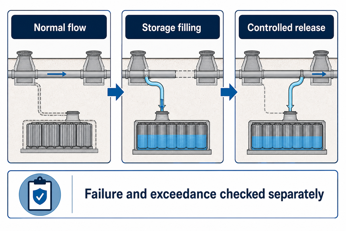
The Three-State Flow Schedule is a 3-State Flow Map that shows normal flow, storage filling and controlled release before failure. Failure and exceedance are checked separately.
How do offline attenuation tanks work?
Offline attenuation tanks divert part of the stormwater flow into separate storage when the main route reaches a defined condition. The tank then releases stored water through a controlled route. The exact configuration for return and control is project specific, and therefore “offline” describes routing in this case rather than design in its entirety.
An example from Oakengates Leisure Centre utilized an offline arrangement to keep flow in a drain-down channel and progressively use storage. That susdrain case study also included access chambers and sediment controls. That example is evidence for the principle, not a standard detail for every project.
Offline storage
Ordinary flow can remain in a separate channel.
A diversion sends higher flow towards storage.
Return flow rejoins at a defined downstream point.
More interfaces may need chambers and level control.
Online storage
The principal drainage flow passes through storage.
Inlet, storage and outlet are directly connected.
Sediment follows the main flow path.
Hydraulic behaviour depends on the same downstream boundary.
Neither design automatically is better. Offline routing can reduce routine sediment entering a stormwater attenuation tank, while online detention can simplify the flow path. The decision depends on levels, water quality, available footprint, maintenance access and how the receiving sewer or watercourse behaves during heavy rainfall.
Use a three-state flow schedule on the drawing: normal flow, storage filling, and controlled release. Add a fourth drawing for failure and exceedance. That last view should show where surface water flows if a pipe blocks, a pump stops, or rainfall exceeds the design event. It ensures a normal-operation drawing isn’t misinterpreted as an entire flood-risk assessment.
Flow Control: Check the Combined Discharge
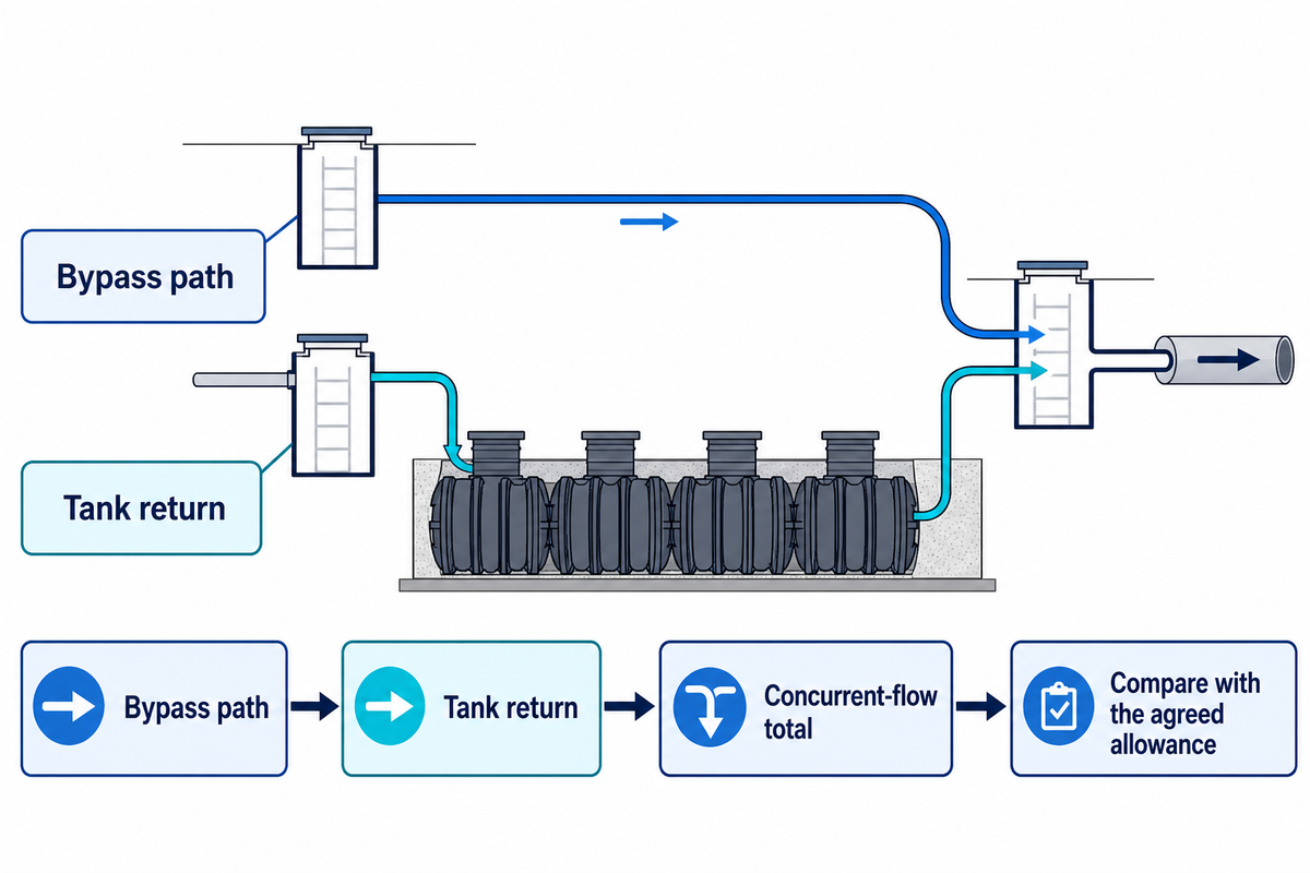
Flow control must be checked at the boundary agreed with the receiving system. If an offline layout has a bypass and a tank return, test whether both can be discharged together. Separate components that appear acceptable can still combine to exceed the allowable limit.
For an illustrative arithmetic check, assume a bypass is discharging 4 L/s and a controlled tank return is discharging 3 L/s. The total discharge is 7 L/s. Against a hypothetical site allowance of 5 L/s, the arrangement exceeds that example limit by 2 L/s. These values are to illustrate an example and aren’t design criteria or selection of a device.
Combined-discharge check
Item
Record
Decision
Receiving boundary
Manhole, sewer system or watercourse point
Agree it with the relevant owner
Bypass path
Peak flow and control basis
Show whether it can overlap tank return
Tank return
Gravity or pumped controlled rate
Check tailwater and failure state
Combined result
Concurrent-flow total
Compare with the agreed allowance
Operating-state evidence schedule
Operating check
Record
Decision
Normal flow
Bypass alone
Confirm ordinary route
Diversion trigger
Level or flow condition
Define filling start
Storage filling
Diverted inflow
Model maximum level
Residual bypass
Flow remaining online
Add concurrent flow
Controlled release
Gravity or pump rate
Check drawdown
Return point
Downstream connection
Sum combined discharge
Blocked outlet
Rising storage level
Map exceedance
Pump loss
No active return
Provide fallback response
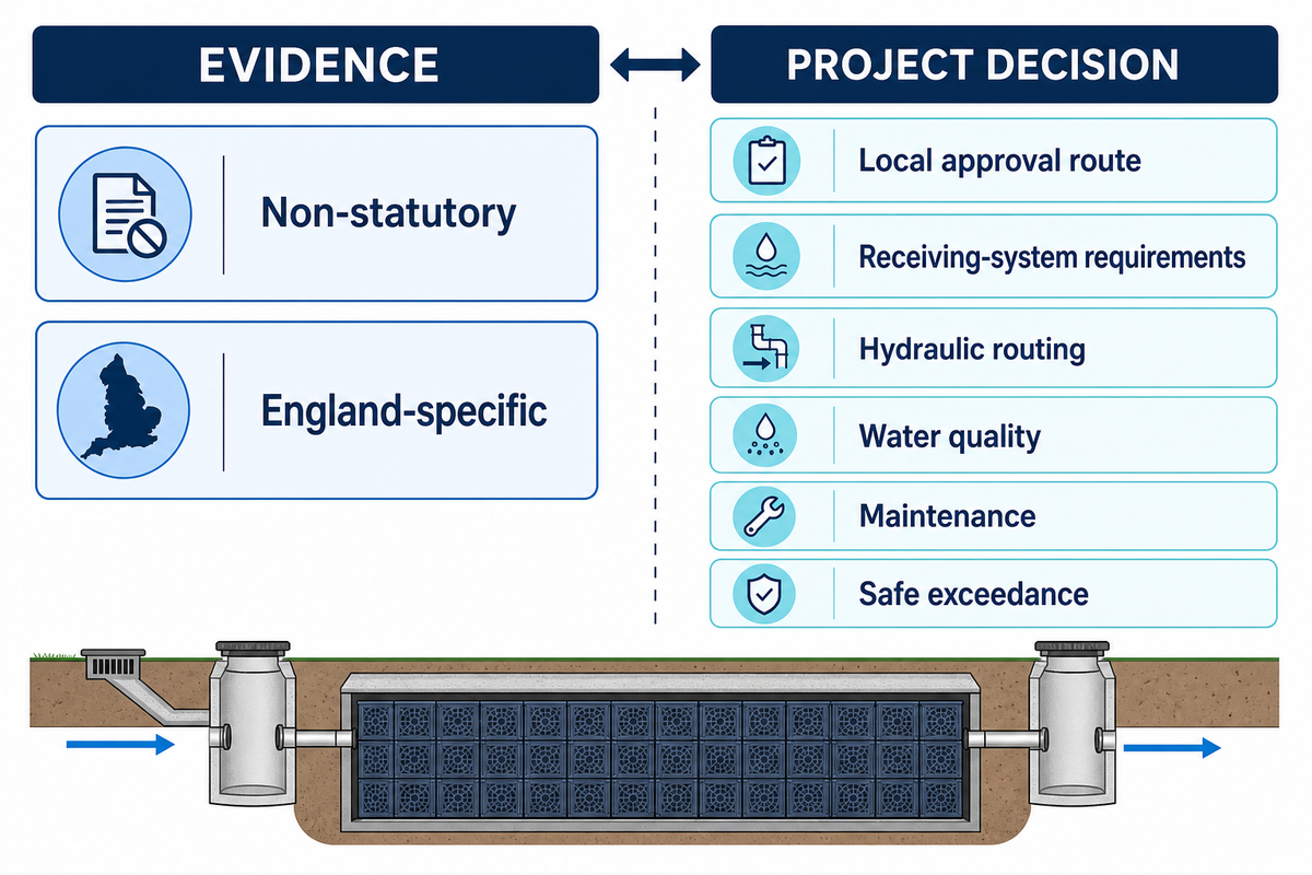
The national standards for sustainable drainage systems in England require that discharge proposals be integrated with the receiving system. They don’t mandate any one specific offline detail. A civil engineering designer should therefore show each branch, the flow control chamber, the hydraulic control and the downstream summation point.
Failure Objection: controlling the release of stormwater during normal operation doesn’t describe what occurs after blockage or pump failure. The current planning guidance on residual flood risk lists blocked conveyance, pumped-system failure and events beyond drainage capacity as examples to assess. Map safe exceedance routes before relying on the flow-control calculation.
Levels and Storage Volume: Make the Tank Fill and Drain
Usable storage is the volume that can fill and drain under modelled level conditions. Gross module volume is only geometry. Invert levels, outlet control, surcharge, groundwater and flood locking, and any other operating level of a pump, can all result in water being left in the bottom of the tank, and/or delaying system recovery before the next storm.
What information do you need to size stormwater attenuation?
Begin with the connected catchment, rainfall model, runoff assumptions, the permitted discharge, and surveyed inlet and outlet levels. Consider tailwater, groundwater, proposed extent and future maintenance route. Route the design events through the drainage system. A single hydrological formula or a supplier’s nominal void ratio cannot replace that model.
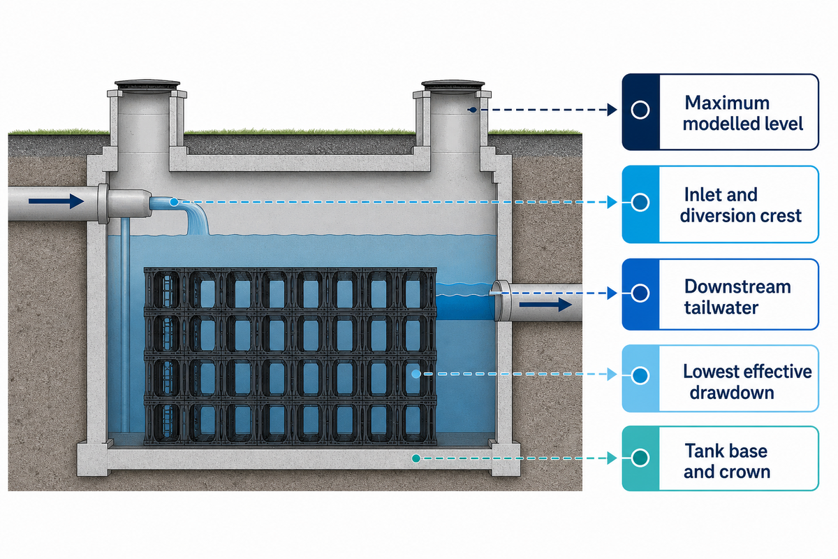
Datum-based level schedule
Level or condition
Why it matters
Evidence to issue
Lowest effective drawdown
Identifies dead storage
Outlet or pump control level
Tank base and crown
Defines physical envelope
Surveyed section and module layout
Inlet and diversion crest
Controls when storage begins filling
Hydraulic profile
Downstream tailwater
Can restrict controlled release
Receiving-system model
Maximum modelled level
Tests freeboard and surface escape
Event results and exceedance plan
Recovery between storms merits its own output. Leeds guidance asks for 50% of storage to be available within 24 hours after a 1-in-30-year event plus climate change, and discusses a subsequent-event check where that criterion is not met. This is a Leeds-specific local requirement, and not a national requirement. It illustrates why final emptying time and initial storage for the next event are separate questions.
Key takeaway
Report gross geometry, net module capacity, modelled usable storage and residual water as four different figures. That separation shows whether the design can hold excess water now and recover enough capacity before a following event.
Silt and Maintenance Access: Keep the System Serviceable
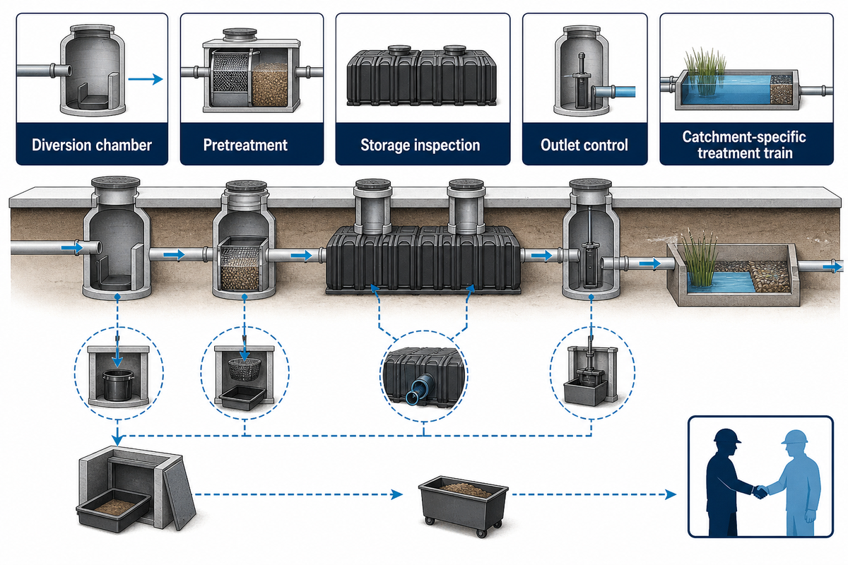
Offline routing can reduce sediment entering storage, but it doesn’t make the tank maintenance-free. The drainage system still requires accessible pretreatment and inspection points, and a route for sediment removal and an owner. The bypass also needs a separate water-quality check because cleaner storage does not prove cleaner discharge.
Susdrain guidance for geocellular storage systems states that the water-quality performance of storage only is poor, and that storage systems require regular inspection and maintenance of silt traps. In practice, specify where solids collect, how a crew reaches them and where removed material goes. Don’t use “access as required” to cover up the means of cleaning.
Maintenance route check
Asset
Inspection question
Required provision
Diversion chamber
Can blockage be seen and cleared?
Safe cover, working space and jetting route
Pretreatment
Where do coarse solids settle?
Reachable sump or treatment device
Storage
Can condition be inspected?
Inspection channel, ports or documented alternative
Outlet control
Can the restriction be serviced?
Isolatable, reachable flow control
Bypass runoff
What treats suspended solids, hydrocarbons or metals?
Catchment-specific treatment train
Surface runoff that bypasses the store may carry pollution even when the storage remains relatively clean. Therefore, water management practices should take into account the entire route from collection to the receiving environment. A silt trap may protect the crate while providing only limited treatment. Environmental protection and maintenance are related but distinct duties.
Crate Selection and Installation: Specify the Whole Build
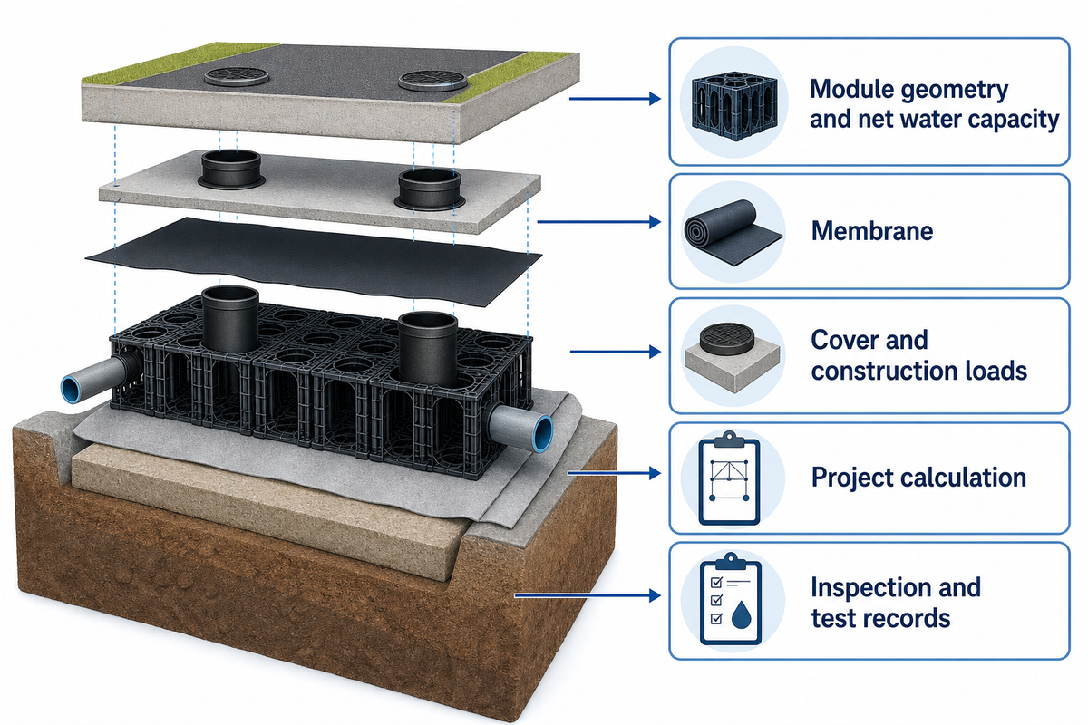
A crate is one part of an installed underground structure. Module geometry and net water capacity help configure the footprint, while cover, lateral restraint, soil, construction loading, long-term behaviour, membrane, groundwater and workmanship determine whether the build is suitable. Product numbers don’t validate an installed underground structure.
Storm Manage publishes two common module sizes in its attenuation tank design and installation guide. Of the StormTank H400 and H500 configurations published by Storm Manage, net storage per module is 190 L and 237.5 L respectively. Their dimensions are 1,000 × 500 × 400 mm and 1,000 × 500 × 500 mm respectively. These are catalog values, and don’t represent installed structural capacity.
Published module geometry and project checks
Model
Published dimensions
Published net capacity
Still to verify
H400
1,000 × 500 × 400 mm
190 L
Loads, cover, soil and installation detail
H500
1,000 × 500 × 500 mm
237.5 L
Loads, cover, soil and installation detail
Ask for evidence related to the design in question rather than a broad certification. Short-term compression results, factory quality certificates and component standards have different scopes. Durability also depends on the load case, control of construction and durable materials around the modular store. A consultant should tailor the design to the specific needs of each project, rather than assign a traffic use to a strength figure in a broad certification.
Published competitor cards attributed to GRAF UK reinforce the same procurement lesson: volume, void ratio and compressive figures may use different bases. Don’t compare figures to Storm Manage net liters as if they were all from the same test. Installing any product below roads or densely built urban areas requires one common structural basis and coordinated temporary works.
Offline Attenuation Tank Cost: Compare the Installed Scope
There’s no universal price premium for an offline attenuation tank to rely on. Cost changes with excavation, storage volume, diversion and return chambers, controls, access, dewatering, membrane, backfill, reinstatement, testing and risk allocation. Compare prices only after all competitors have priced the same drawings, assumptions and exclusions.
How much does an offline attenuation tank cost?
Investing in an attenuation tank on crate price alone hides most of the installed work. Offline routing may add chambers or controls, yet it may also change cleaning access or excavation geometry. The result may only be cost-effective if the scope matches the site. A low unit price isn’t necessarily a cost-effective solution for stormwater management.
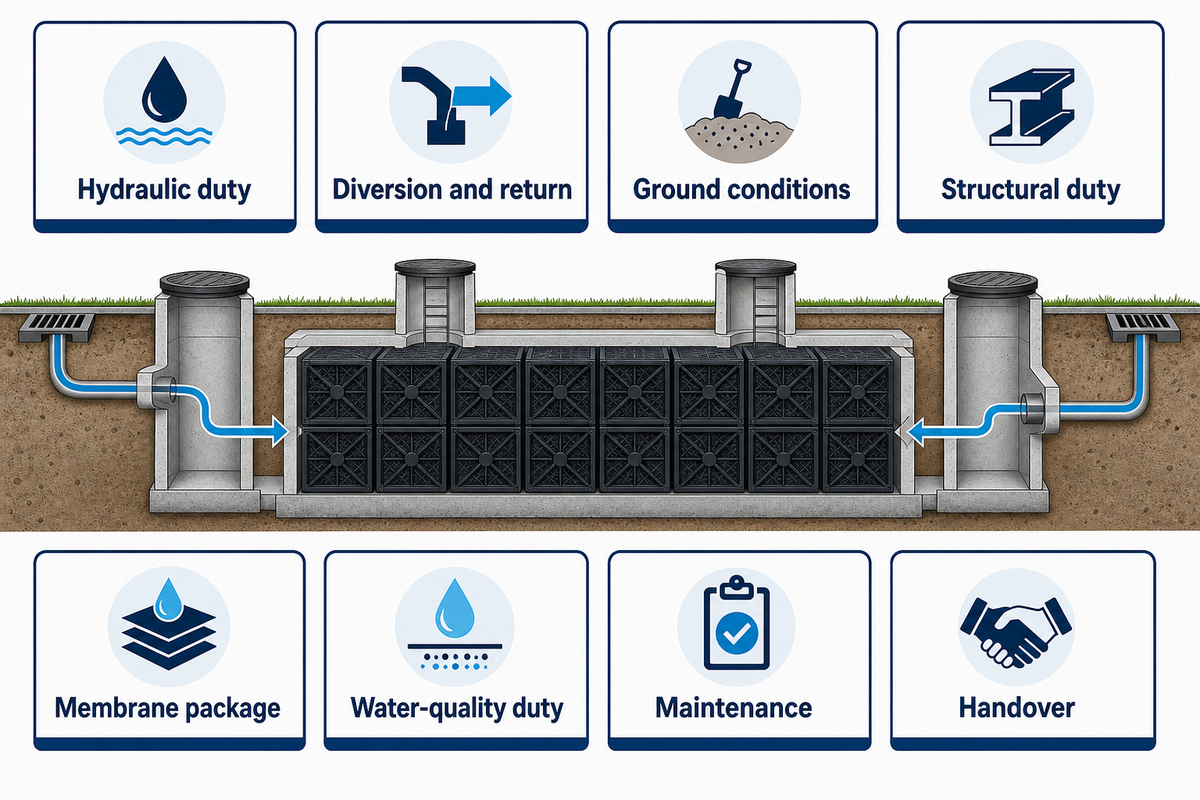
Scope-Matched Quote Sheet
Scope category
Supplier input
Verification
Hydraulic duty
Usable volume, flows and levels
Model report and long section
Diversion and return
Chambers, weirs, controls and pumps
General arrangement and control schedule
Ground conditions
Excavation, base, dewatering and backfill
Ground investigation
Structural duty
Cover, traffic and construction loads
Project calculation
Membrane package
Impermeable liner, protection and joints
Method statement and test plan
Water-quality duty
Pretreatment and bypass treatment boundary
Treatment design basis and maintenance owner
Maintenance
Silt access, inspection and cleaning
Access drawing and operating manual
Handover
Testing, records, training and warranty scope
Named deliverable schedule
Use the same basis and program for all bids. For each bid, confirm if excess water management, temporary pumping and wastewater from cleaning are included. Use the same rainfall basis, programme, haul distance and reinstatement boundary in every bid. For more budgeting context, use the attenuation tank cost guide, then return to the project-specific quote sheet before making an award.
Establish a procurement hold point before the preferred bidder is appointed. At that point, the modelled storage, level schedule, structural calculation basis, membrane details, inspection route and maintenance funding should name an owner and an acceptance document. This prevents a quote from appearing complete while a chamber, control, temporary work or long-term duty remains outside every package.
Supplier Evidence: Assign Every Package Interface
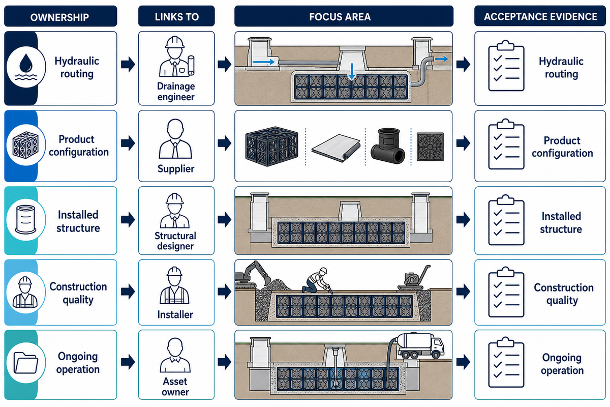
A complete submittal assigns each interface to a named party. The module supplier can provide product data; the drainage designer owns hydraulic performance; the structural designer checks the installed load case; the installer owns method and records; the asset owner accepts access and maintenance duties.
Responsibility matrix
Interface
Primary owner
Acceptance evidence
Hydraulic routing
Drainage engineer
Model, levels and exceedance drawing
Product configuration
Supplier
Model schedule and declared properties
Installed structure
Structural designer
Project calculation and details
Construction quality
Installer
Inspection and test records
Ongoing operation
Asset owner
Funded maintenance plan
This matrix enables local authorities and the client to distinguish a product offer from an approved sustainable water management scheme. Stormwater systems need coordinated management strategies to reduce the likelihood of uncontrolled flooding and safeguard local ecosystems. The supplier can help achieve that, but can’t sign off on every discipline’s work.
Attenuation tanks play one role in broader stormwater management. A solution for stormwater management may also need source control, treatment, infiltration, conveyance and safe exceedance. For supplier context without replacing project design, review the StormTank attenuation range and the existing attenuation supplier comparison.
What Is Changing in UK Stormwater Design?
Current requirements must be checked by jurisdiction before an attenuation package is fixed. England published non-statutory national sustainable-drainage standards on 19 June 2025, and updated the publication page on 30 July 2025. They’re England-specific, and don’t create a single approval route across the UK.
The standards cover integrated planning, runoff destination, flood performance, water quality, amenity, biodiversity and maintenance. That guidance is supportive of resilient and sustainable urban developments, but doesn’t specify online or offline storage for a site. Local planning conditions, sewer-owner requirements and current regulations and guidelines still need checking.
For residential developments, schools, logistics sites and other occupied places, the risk of flooding must be assessed for people, property and access routes that could be affected. An underground store doesn’t eliminate surface exceedance. The design team should show where water travels when capacity is exceeded and who keeps that route unobstructed.
Changing weather can alter the design inputs used to manage stormwater. Changes to rainfall and hydrological assumptions are made to revise the design, not to enlarge a tank by an arbitrary percentage. Mitigating flood risk and reducing the risk of erosion require safe surface routes and receiving-system checks. A partial design solution is to use a controlled release from storage.
Offline Attenuation Tank FAQs
Is an attenuation tank a soakaway?
View answer
No. An attenuation tank temporarily stores rainwater and releases it at a controlled rate. A soakaway uses infiltration to discharge water into suitable ground. Both may use modular crates, but their liners, hydraulic destinations and ground-investigation needs differ. An offline tank also needs its diversion and return routes defined. See the detailed soakaway versus attenuation comparison.
Can attenuation tanks improve water quality?
View answer
Storage can settle some material and protect downstream flow, but a geocellular store isn’t automatically a treatment device. Catchment hazards determine the treatment train. An offline store may collect less routine silt, while its bypass carries stormwater runoff that still needs appropriate controls. Confirm pretreatment, bypass treatment and maintenance access as separate duties. The designer should trace pollutants through both branches and state which component treats each operating condition.
How close can a stormwater attenuation system be to a building?
View answer
There’s no universal separation that suits every project. The designer should assess excavation stability, foundations, utilities, groundwater, access, leakage consequences and the structural influence zone. Planning and building-control requirements may also apply. Record the accepted distance on the coordinated site plan and make sure construction plant, inspection chambers and future cleaning access still fit. Check the temporary excavation as carefully as the permanent tank: shoring, dewatering and plant loads can affect nearby structures before the completed system carries any water. The accepted arrangement should appear on coordinated civil, structural and utility drawings. That coordination also covers emergency access, future utility work and later changes to the building or paved loading above.
What is the purpose of a retention tank?
View answer
A retention tank keeps water for later reuse or another continuing function. Detention and attenuation normally describe temporarily storing runoff and releasing it under control. Project terminology varies, so the drawings should state the intended water balance, normal operating level, overflow condition and discharge route rather than relying on the label alone.
Are there regulations I should be aware of before installing an attenuation tank?
View answer
Yes. Check the applicable planning policy, drainage approval route, receiving sewer or watercourse consent, current sustainable-drainage standards, building constraints, health and safety duties and environmental permits. Requirements vary by UK nation and local authority. Product data doesn’t replace hydraulic, structural or geotechnical design, and the maintenance owner should accept the operating plan before construction.
Evidence note: Product dimensions are published by manufacturers, and regulatory statements vary by jurisdiction. The worked flow sum is illustrative and not a design value for the project.
Issue a scope that suppliers can price
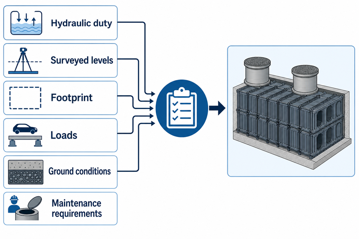
Send Storm Manage the hydraulic duty, surveyed levels, footprint, loads, ground conditions and maintenance requirements. The team can configure a module package against that project basis.