We use the details you submit to review and respond to your project enquiry. Entries are handled in this website’s WordPress database using Fluent Forms; our hosting and email providers may process the submitted details. Other technical providers receive only the data described in our Privacy Policy.
Please do not send passwords, payment-card details, government identification numbers, sensitive personal data, or unnecessary confidential third-party information.
Stormwater Detention Tank Cost & Sizing is fundamentally a two-part engineering exercise: calculate the storage volume a site’s discharge limit requires, then price the system that delivers it. Those decisions often get made twice on a project – first, on a spreadsheet prior to permits, then second, when the contractor’s bid comes back higher than what the engineer originally estimated. This guide walks through the actual calculation engineers use to size a tank, the elements that influence its cost, and the most common errors that lead to a project exceeding its budget and/or schedule. This process applies regardless of whether you end up installing a pre-cast vault, a geocellular crate system or a larger than expected pipe.
In essence, the volume of a stormwater detention tank is dictated by a required maximum outflow, rather than a preference for the tank size – you simply compute the difference between how much water flows in and how much the local code allows to flow out over the course of a storm that maximizes that difference. In general, the installed price of underground systems commonly runs from the high single digits into the high $20s per cubic foot ($8-$28 is the typical band) depending on the system type, excavation requirements, and access, and the single biggest cost lever most engineers underuse is right-sizing the calculation itself rather than defaulting to a conservative oversized number.
Quick Specs
Typical design life
50 years for precast concrete and modern geocellular systems (design-basis figure, not a warranty term)
Void ratio range
~30-40% gravel bed · ~80% oversized pipe · up to ~95% geocellular/plastic-grid
≈200 acres (TxDOT); larger or complex sites need a hydrograph/routing method
Excavation share of budget
Commonly 20-30% of total installed cost, more on rock/high-groundwater sites
What Is a Stormwater Detention Tank (and How It Differs From Retention)?
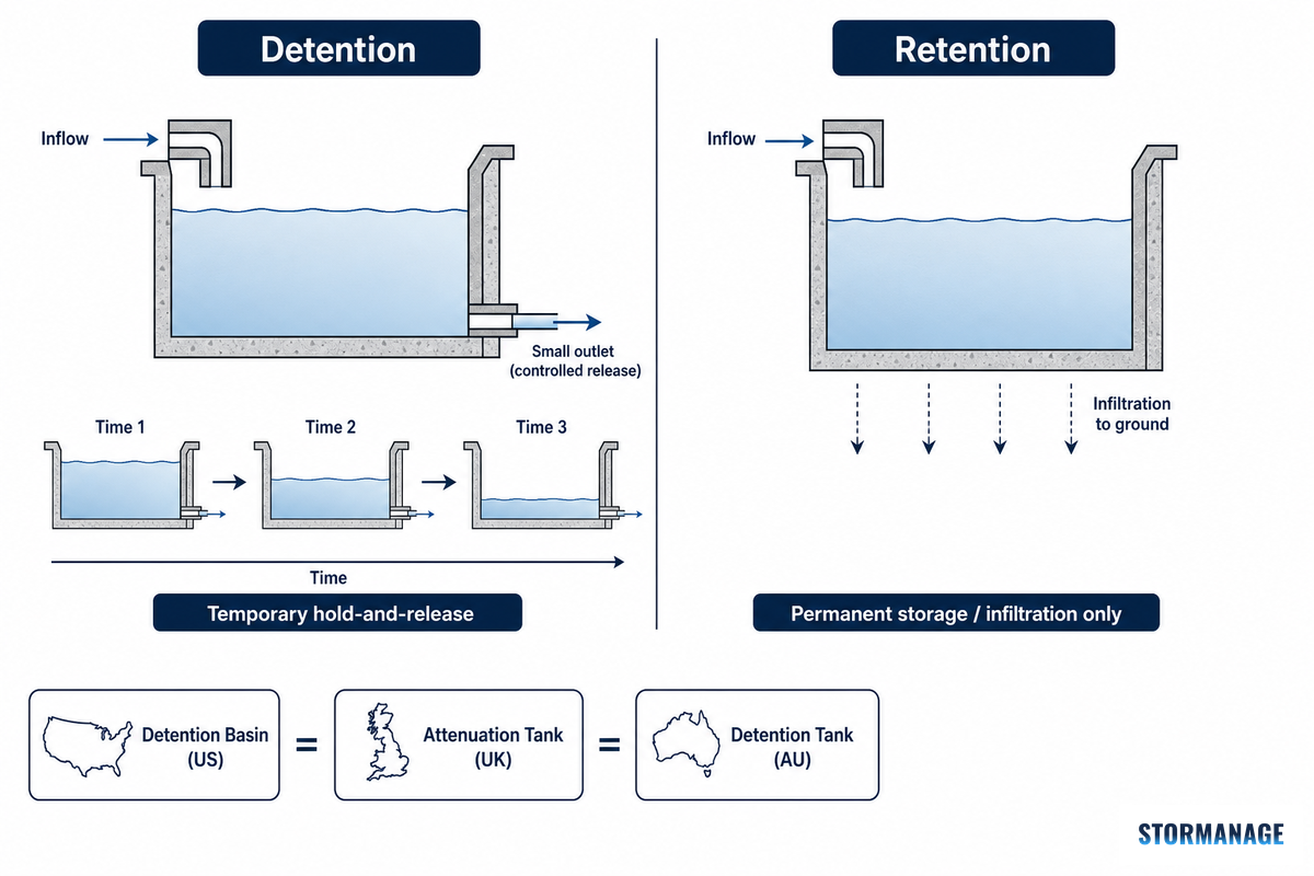
A stormwater detention tank is an underground structure that temporarily holds runoff and releases it at a controlled rate through a restricted outlet, so a downstream storm sewer or channel never sees more flow after your project is built than it saw before. That’s the whole job: shave the peak, not store the water forever.
A retention system, by contrast, is designed to hold water permanently or release it primarily through infiltration or evaporation rather than a timed outlet — the distinction matters for permitting, because most municipal codes size detention and retention against different criteria entirely. EPA’s post-construction stormwater program guidance reflects this same detention-versus-retention split at the federal level.
What’s the Difference Between Detention and Retention?
A detention tank slows water down: it collects runoff during a storm and releases it over several hours to days through an orifice, meeting a maximum outflow rate set by your local drainage authority. A retention basin or infiltration system, in contrast, is sized for storage capacity – the water seeps into the ground or evaporates, with no engineered release rate involved.
Confusing the two in a stormwater detention tank design submittal is an easy, avoidable mistake: if your permit application includes terms like “release rate” or “orifice diameter,” you’re dealing with detention sizing, while “infiltration tests” and “percolation rate” point to retention/infiltration – these calculations aren’t transferable, because the two systems are engineered against fundamentally different criteria (a timed discharge rate versus a soil percolation rate). Get “stormwater detention vs retention” wrong on the application and expect your reviewing authority to send it back.
There’s another catch you should be aware of prior to breaking out the slide rule: the very same underground system is named something else if you’re reading codes in another country. US engineer calls it a “detention tank” and sizes it against EPA/municipal post-construction discharge guidelines. UK engineer calls it an “attenuation tank” and sizes it against SuDS design guidelines for a identical geocellular crate system.
Australian engineer calls it an “OSD tank” (on-site detention) and designs against state/council OSD manual requirements. The actual hardware may look exactly the same (the identical manufacturers are likely supplying all three named systems), however the sizing approach, lexicon and approval pathway varies considerably by nation, so be warned not to directly substitute a specification developed in the US for a European job.
Underground Detention System Types: Concrete Vaults, Geocellular Crates, and Pipe Storage
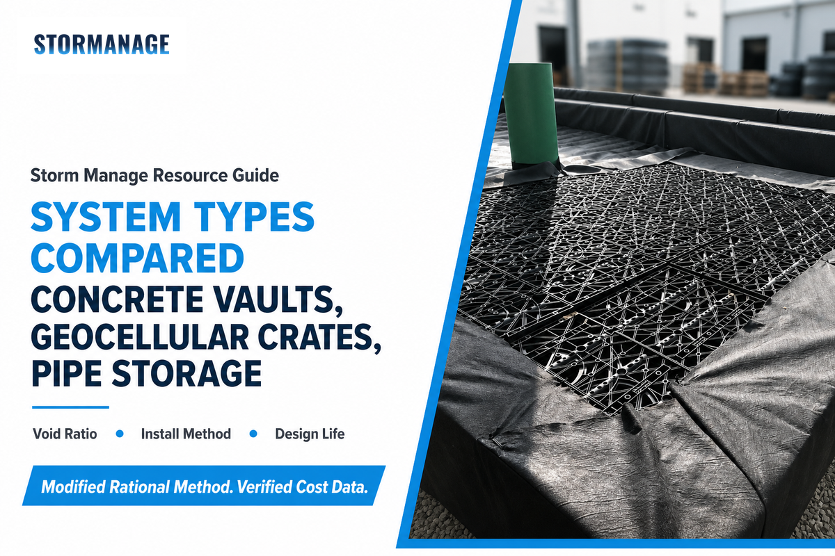
Most underground detention projects can fall into one of four systems: precast/cast-in-place concrete vaults, geocellular/modular plastic crate systems, oversized/corrugated pipe storage and gravel-bed trench storage. Determining which one will work best has less to do with cost per cubic foot in and of itself and more with how much earth you’ll have to move to meet the required volume – a matter of the void ratio, or what percentage of a system’s total footprints actually represents water storage space.
9 underground stormwater storage system types compared: geocellular crate systems reach roughly 95% void ratio, nearly triple an unwrapped gravel trench’s 30-40%, which directly cuts excavation volume for the same stored capacity.
System type
Typical void ratio
Structural profile
Best fit
Precast concrete vault
~90-95%
Highest load capacity, factory QC, fastest install of the concrete options
Sites needing H-20 traffic rating with minimal cover depth
Cast-in-place concrete vault
~90-95%
Custom geometry, longest track record, slowest to build
Irregular footprints that off-the-shelf precast can’t match
Geocellular/plastic-grid crate
Up to ~95%
Low unit weight, hand-set installation, no crane needed
Higher load capacity than HDPE at large diameters, corrosion-protection needed in aggressive soils
Deep-burial or heavy-load linear runs
Above-ground/prefabricated tank
~95-98%
No excavation for the tank itself, exposed to weather/UV
Small residential or industrial sites with surface space to spare
Geotextile-wrapped gravel trench
~35-40%
Fabric separation reduces fines migration into voids over time
Retrofits where a wrapped system extends serviceable life over unwrapped gravel
Unwrapped gravel-bed trench
~30-40%
Lowest capital cost per unit material, simplest to inspect, most excavation per CF stored
Small residential sites, low-budget retrofits
The void ratio isn’t just an interesting statistic; it actually influences your actual excavation depth. A system that can hold 95% of its volume in actual stored water requires about a third of the dig to meet the same storage target as a gravel trench with a void ratio of 30-40% because you aren’t digging and backfilling space that never held water. When digging costs are already at a premium (rock, groundwater or difficult urban sites) the costs mount quickly.
📐Engineering Note
Modular plastic crate systems are at a lower stage of design code maturity in the US market compared to precast concrete design codes – verify the basis of a manufacturer’s load-rating test (AASHTO wheel-load or equivalent) and not assume all crate products are of the same structural heritage, especially if installed in drive lanes and traffic from heavier vehicles.
Two recent US patents show where crate-system design is still moving: US Patent 12,371,891 (Advanced Drainage Systems, issued July 2025) includes internal trusses for resistance against lateral loads, and US Patent 12,305,380 (also Advanced Drainage Systems, issued May 2025) employs tapered columns and arched side walls to provide resistance to loads – both patents filed within the last three years, which tells you the crate manufacturers themselves still consider the basic box structure an open engineering problem worth actively improving, not a settled design. That context matters for the failure case in the next section.
How to Size a Stormwater Detention Tank: The Calculation Walkthrough
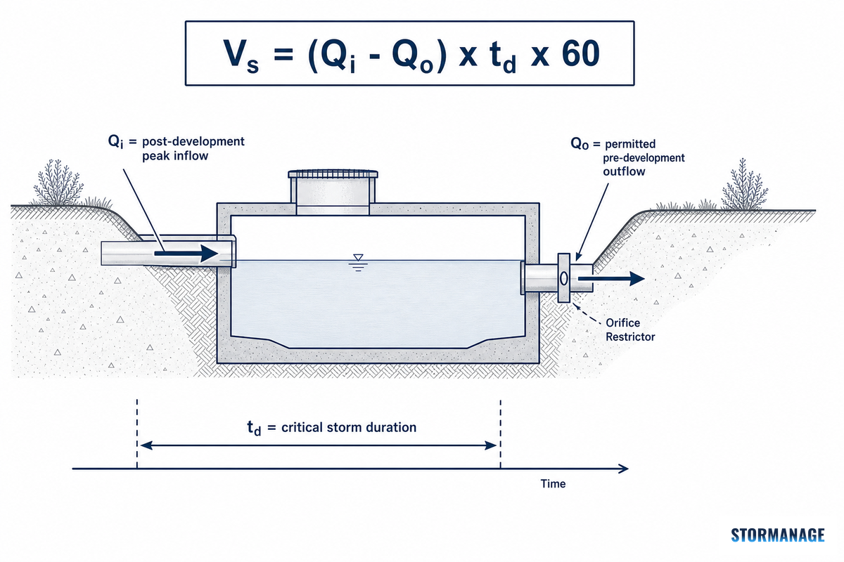
The most commonly taught detention pond sizing and small-to-medium tank design methodology is the Modified Rational Method. It’s a modification of the basic Rational Method (Q = C × i × A – for calculating only peak flows of stormwater runoff, like pipe sizes) into a storage volume method:
A quick unit check: the “× 60” belongs in the formula only when td is expressed in minutes (60 seconds per minute converts cfs-times-minutes into cubic feet). Some reference guides state the same relationship with td in hours and a ×3,600 factor instead – same underlying physics, different time unit. Whichever version your local handbook uses, keep the same units through your entire calculation rather than mixing references.
What Is the Rational Method Formula?
The Rational Method (Q = C × i × A) estimates peak runoff rate from a drainage area: C is a runoff coefficient describing how much rainfall becomes runoff, i is rainfall intensity in inches per hour, and A is drainage area in acres. It produces a single peak flow number, not a volume.
That single-number limit is exactly why detention sizing needs the “Modified” version layered on top: C typically runs 0.15-0.25 for lawns and 0.85-0.95 for pavement and roofs, and the method gets run twice – once for pre-development conditions, once for post-development – using two Rational Method results rather than one.
Here’s a worked example using realistic numbers for a small commercial site and a single design storm event. Picture a 3-acre parking and building development with a post-development runoff coefficient of 0.85 (mostly pavement and roof) and a design rainfall intensity of 5.5 in/hr at the critical duration:
Pre-development allowable outflow: using the site’s pre-development runoff coefficient (0.25, undeveloped meadow) against that same 5.5 in/hr figure: Qo = 0.25 × 5.5 × 3 ≈ 4.1 cfs, this is the release rate your local code will require you to hold to (the same discharge control logic applies whether you’re comparing post-development peak discharge against a pre-development baseline, or checking a 100-year storm overflow condition separately)
Critical storm duration: for this example, 20 minutes produces the largest storage requirement when multiple durations are tested (in practice, you run this calculation across several durations and take the maximum, that’s what makes it “critical”)
Required storage volume: Vs = (14.0 − 4.1) × 20 × 60 = 9.9 × 1,200 ≈ 11,880 cubic feet (about 336 cubic meters, if your local manual works in metric) – this is the tank volume you’re now sizing modules or a vault against
From there, the outlet orifice gets sized to physically restrict flow to that 4.1 cfs target using the standard orifice equation (Q = Cd × A × √(2gh)) – this outlet structure design step is where a civil/drainage engineer solves for orifice area A given your site’s available head h. This is also the step where King County’s and NYC DEP’s design manuals both apply an important constraint worth internalizing: water quality treatment volume, infiltration, and reuse requirements can reduce the required detention volume, but nothing is allowed to increase the maximum permitted release rate above what the pre-development peak discharge supports.
A few related terms worth knowing before you talk to a reviewing engineer. Catchment area (sometimes called drainage area or tributary area) is the land that sheds runoff toward your tank – get this boundary wrong and every downstream number is wrong too. Time of concentration is the time it takes runoff from the farthest point in that catchment area to reach the tank inlet, and it directly affects which design storm duration controls your calculation. Some jurisdictions also require a curve number (from the SCS/NRCS method) instead of, or alongside, a runoff coefficient for larger or more complex sites – if your reviewing manual asks for a curve number, that’s a signal you’re outside simple Rational Method territory. Two more terms that show up on submittal checklists: freeboard (extra depth above the design water surface, a safety margin most manuals require as minimum detention above the calculated volume of water) and extended detention (a design that holds water longer than the minimum drawdown window, often for additional water quality treatment credit). If your site characteristics push a larger development project toward a rainfall events analysis using real historical rainfall records rather than a single design storm, or if controlled-release requirements change between review cycles, expect your tank configuration or overall detention tank system layout to move too – none of these numbers are set once and forgotten.
⚠️Where This Method Stops Working
The Rational Method family has real limits. Texas DOT’s hydraulics manual explicitly states the method “provides the designer with a peak discharge value, but does not provide a time series of flow nor flow volume” and it doesn’t account for storage in the drainage area, instead assuming available storage just fills. TxDOT limits its use to 200 acres, and if you have a storage feature large enough to not fully fill in the design storm, you should use a hydrograph or routing method (SCS TR-55, SWMM, or equivalent modeling software) and not a hand calculation. If your reviewing jurisdiction’s manual specifies a different method, then use the method required by your manual – local design criteria manuals override general formulas. This is standard engineering hydrology practice, not a shortcut you can skip because the Rational Method felt simpler on your last project.
Need a project-specific number without doing the math yourself? Storm Manage’s module layout calculator can convert a volume target into a number of modules once you’ve determined the storage volume needed, or for an even faster estimate if you’d like to start at the source, get an instant sizing estimate from Storm Manage’s detention tank cost and sizing tool.
Where the Cost Actually Goes: Material, Excavation, and Site-Condition Drivers
Industry cost guidance – including EPA’s fact sheets on on-site underground storage – generally place fully installed underground detention costs within a wide band of $8-28/cu.ft. of storage, with most of that variation explained by three factors: type of system, difficulty of excavation, and local rates for labor/materials. For current purposes (2026), consider any bid older than 6-12 months out of date and verify pricing before it drives any budget decisions, as construction pricing has varied substantially in recent years.
Where the Money Actually Goes
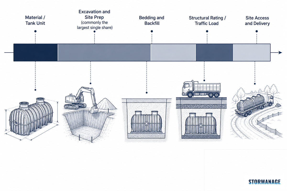
Excavation and site prep-usually 20-30% of total installed cost. This is commonly the largest line item.
The void ratio of the system. A low-void system, such as gravel, will require roughly 2-3x the excavation of a high-void system (like geocellular systems) to achieve the same stored volume. Excavation costs more than storage product itself.
The “gotcha” factors encountered after you start digging. Most projects have site-specific challenges – rock, perched groundwater, or contaminated fill are common reasons for change orders. Hard excavation and rock removal alone can add $5,000-$15,000+ to a project’s cost, making an upfront $2,000-$5,000 boring report a prudent investment.
Required structural rating. If the storage facility is installed under an H-20 rated traffic area, it will be more expensive per cubic foot than a pedestrian or landscape facility with shallower cover.
In practice, if you receive a bid 20-30% higher than you expected based on the general range above, don’t assume it’s automatically incorrect. Instead, ask for clarification on the geotechnical findings and the extent to which the discrepancy is due to excavation versus the storage system. For an estimate breakdown for a specific product line in a particular region, use Storm Manage’s installed cost stack tool to estimate the breakdown of these costs.
Underground Tank vs. Surface Detention Pond: Which Actually Costs Less?
On construction cost alone, a surface detention pond is almost always the winner – an open excavation and grass-lined basin costs far less to build than the same storage volume placed underground. But construction cost isn’t the right metric to compare in isolation, because a surface pond and an underground tank use the site in very different ways.
When land is expensive or limited in supply, an underground tank often proves the more economical choice once you weigh the overall project, not just the concrete or crates. King County’s Surface Water Design Manual allows both approaches under the same flow-control framework, so the choice comes down to site economics, not a regulatory preference for one over the other.
Underground detention tank vs. surface pond: underground storage costs more per cubic foot but returns the surface for parking, building footprint, or leasable area.
Factor
Surface detention pond
Underground tank
Construction cost/CF
Lowest of any option
Roughly 8-25x a basic surface pond, per industry cost guidance
Surface land use
Consumes buildable/leasable/parking land permanently
Returns the surface for parking, building footprint, or green space
Lower routine cost, but requires scheduled inspection access (see maintenance section)
Best fit
Rural/suburban sites with low land value, larger parcels
Urban/dense sites where surface land has real dollar value
“The main reason to consider underground detention is the return on investment on the value of the increased land or building capture. There are increased capital costs initially compared to a surface solution, but underground detention provides more outdoor storage and the opportunity for increased building sizes and larger parking lots.”
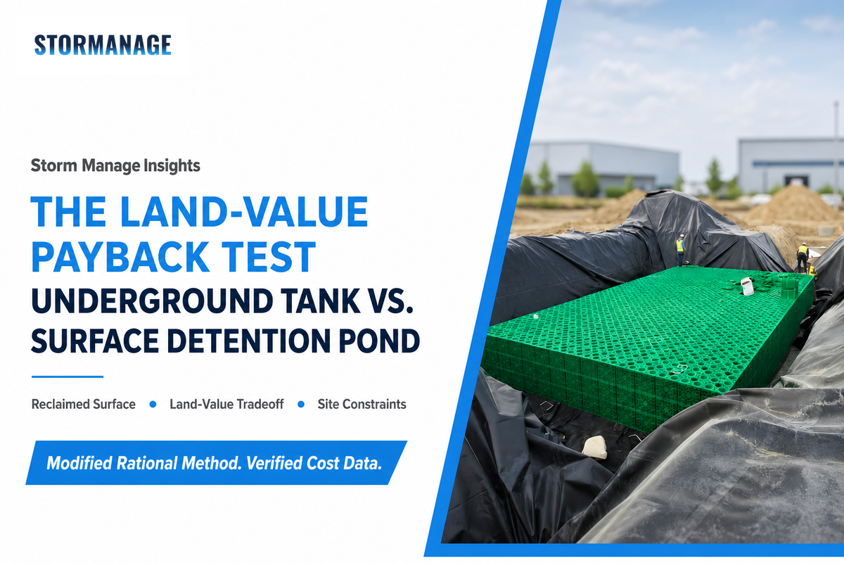
💡The Land-Value Payback Test
Prior to opting for the more inexpensive construction costs associated with a surface pond, calculate one simple comparison: what is the value (through sale, lease, or avoidance of land acquisition costs) of the surface area a pond would consume versus the additional construction cost of placing that storage underground? On a property with significant market value for land, the cost premium for an underground storage tank is as a default less than the value gained from reclaiming surface space-this follows the CREDA principle explained earlier, acting as a straightforward check rather than a fixed monetary amount, given the variability of land costs from one market to the next.
Why Your Discharge Limit Decides Your Tank Size (Regulatory Drivers, US + UK)
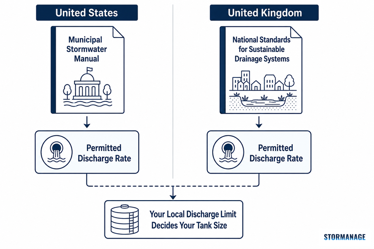
Every stormwater detention calculation begins with a number you don’t control: the maximum permissible discharge rate your local drainage authority sets for the site. Find this number first, before calculating any volumes – it’s “Qo” in the preceding equation, and it comes from local ordinance, not engineering judgment.
The risk in practice: assuming a national or “typical” discharge standard applies, rather than pulling the actual local number first, can force a completed volume calculation to be redone once the real jurisdictional figure surfaces at plan review – a costly, avoidable mistake, and one more likely on multi-site portfolios where a discharge rate from one city or county gets carried over to a different jurisdiction without re-checking it. Storm Manage operates product hubs built around exactly this range of jurisdictions – US EPA/LID, UK SuDS, and Australian OSD terminology – which is part of why this guide treats “find your local number first” as step zero, not an afterthought.
Who Sets the Allowable Discharge Rate for My Site?
In the United States, your city or county’s Stormwater/Drainage Manual most often sets the permissible discharge rate, typically matched to the pre-development peak runoff flow for a given design storm (commonly the 10-year storm for the release-rate calculation, with the 100-year event checked separately for emergency overflow).
King County, Washington’s Surface Water Design Manual is a real, current example of how specific these rules get: detention tank inverts must sit at least 0.5 feet below the connecting inlet and outlet piping, with flow-through design and in-line access for sediment removal, amended as recently as 2024 – a universal national guideline can’t substitute for reading the actual local code.
UK practice embeds a similar limitation within Sustainable Drainage Systems (SuDS) guidance, not a single national rate table. To be very specific, at the time of this writing, as to where that regulation currently stands: Schedule 3 of the Flood and Water Management Act 2010, the provision that would make SuDS a hard statutory requirement in England, hasn’t been commenced. Government is following a planning-policy route, and Defra’s own National Standards for Sustainable Drainage Systems (June 19, 2025) identifies itself explicitly as “non-statutory standards” which are to be used by local planning authorities in their decision-making processes without independent legal authority. In the English market, consider SuDS compliance as a planning-policy and local-authority-approval question, rather than as a directly enforceable national law — the direction is there, the mechanism isn’t.
Also at this stage, consider comparing the sizing methodology you’re using to the requirements of the jurisdiction. Many municipal design manuals throughout the US, as well as the TxDOT guidelines already discussed, will require, or at a minimum prefer, a hydrograph/routing methodology over the simplistic Rational Method once a given project exceeds certain size or complexity thresholds. Verify your reviewer’s preferred methodology prior to dedicating engineering effort to a calculation they won’t accept.
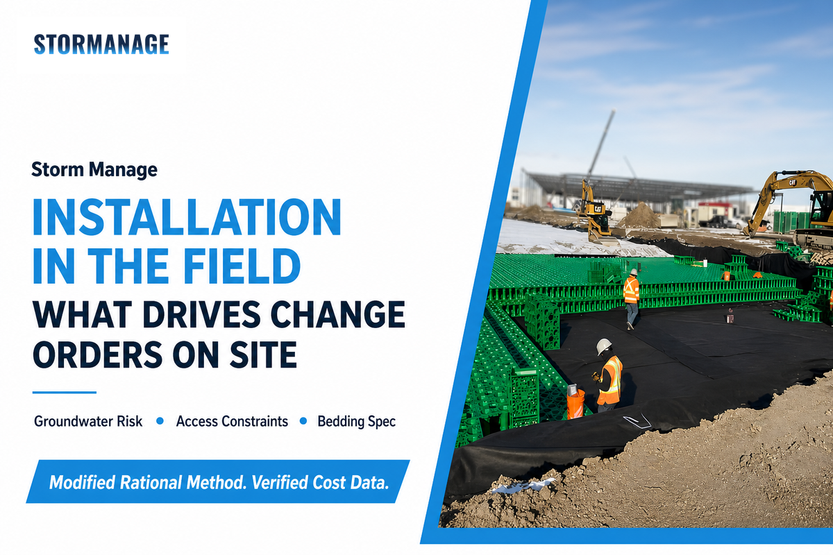
Installation and Excavation: What Drives Change Orders
Detention tank installations are more likely to be disrupted not by the tank itself but by events discovered during excavation. Four factors consistently drive cost overruns for detention tanks:
✔ What Reduces Risk
Pre-bid geotechnical borings (2 to 4 borings to excavation depth plus 5 ft. penetration, generally $2,000-$5,000 total)
Confirming groundwater depth relative to invert elevation
Verifying site access for heavy delivery equipment when selecting large pre-cast systems
⚠ What Causes Overruns
Discoveries during excavation such as unanticipated rock, contaminated fill, or a perched water table
Use of structural systems requiring lifting equipment/cranes in restricted site conditions
Failure to address potential long-term deformation risk of certain plastic systems during bid (see the following section.)
Even after a detention tank is installed and backfilled and the surface is paved over, structural design and analysis continue, since the tank continues to carry live and dead loads over its entire design life – not just the brief duration of construction, the mode of failure described below. This is the same long-service-life thinking behind design manuals like NYC DEP’s detention facility design criteria: a tank engineered for decades of service has to be built and inspected with that full service life in mind, not just the day it passes initial backfill.
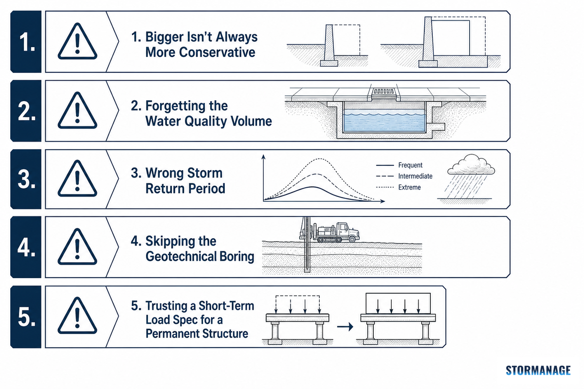
5 Sizing and Costing Mistakes That Blow the Budget
The vast majority of cost overruns and rejected permit applications for detention projects result from one or more of a small handful of repeated errors. Here are the five most commonly seen errors in professional practice and in case studies.
The 5 Sizing and Costing Mistakes That Blow the Budget
Let’s take the premise “bigger is always more conservative.” This is just not true. Consider a representative scenario, illustrative rather than a specific documented project: on an 11-acre commercial parking lot, a simplified sizing method grossly over-designs the required facility to 54,000 cu. ft. A detailed, site-specific hydrologic analysis by an outside engineering consultant instead right-sizes it to about 44,000 cu ft – roughly an 18% cut in tank volume that, at this guide’s own commonly-cited $8-28/cu.ft. installed-cost range, works out to tens of thousands of dollars in avoided cost, while staying code-compliant.
There’s also a genuinely counter-intuitive property here: overestimating the pre-development peak flow rate makes a detention facility smaller, not larger, because it raises the permitted release rate. Conservative inputs don’t automatically fail safe the same way they do in the pipe-sizing example.
Forgetting a water quality volume. Often, detention volume (rate control) and water quality volume (pollutant control, sized for a smaller “first flush” storm event) have two separate numbers with the same code – NYC DEP’s detention facility criteria is one real example of a code that treats reuse, infiltration, and recycling credits as reductions to detention volume specifically, not water quality volume – and new engineers unfamiliar with a specific jurisdiction can size only one and have to redo the plans.
Incorrect storm return period for design basis. Verify with your reviewing authority which return period to use for calculation of release rate (as a rule the 10-year) vs that for the overflow/emergency design (usually the 100-year), mixing the two leads to a vastly under or oversized primary system.
Skipping the boring to give the developer an up-front $2,000-$5,000 saving. Most frequently quoted reasons for detention-project change orders – rock, polluted fill, perched water – all are “discovered” when the boring program “wasn’t in the budget” turns out to be cheaper than one change order.
Relying on a manufacturer’s short-term load spec for a permanently buried structure. See the case study below – the failure show up months after everybody’s signed off, not during construction.
“A small irregular compression load on the plastic box will result in out-of-plane deflection, which will continue to increase until the sides of the box buckle.”
Tawresey’s ASCE article recounts a specific, named case in detail, offered here as a reported example rather than something independently investigated for this guide: a church site’s plastic-crate detention system, per the article, built from 26,000 cubic feet of storage in individual 16x18x27-inch boxes (4.2 CF each) in two layers under a 94,500-square-foot parking lot, buried 9.5 feet deep. The system reportedly passed initial loading without issue, and the parking lot is described as beginning to settle four months later. Tawresey attributes the root cause to thermoplastic creep – permanent, progressive deformation of the polypropylene boxes under sustained (not initial) load – which he argues the manufacturer’s own literature — “creep after 90 days should be 0.40%” — didn’t adequately capture for a structure meant to carry load indefinitely. Whether or not every detail of that specific project is independently verifiable from this guide’s vantage point, the underlying engineering lesson stands on its own: a buried structure’s long-term creep behavior under sustained load is a distinct engineering question from its initial load rating, and it deserves its own line of due diligence before you sign off on a product.
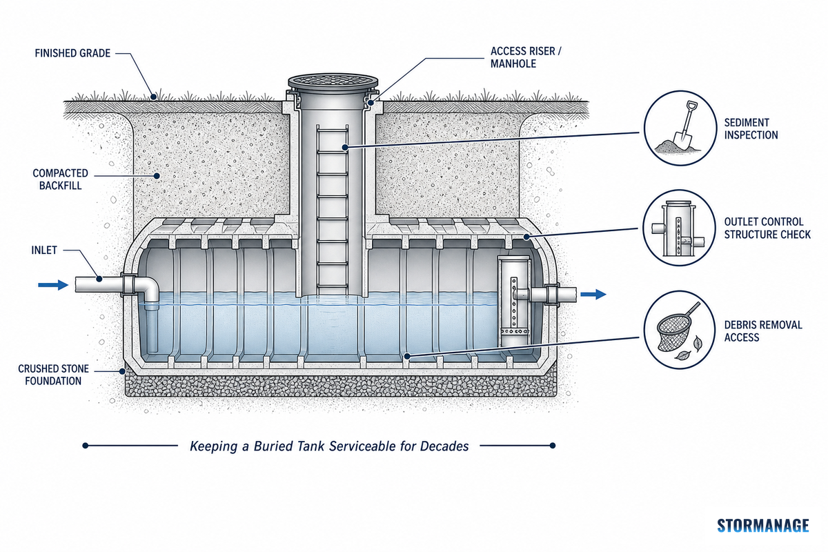
Maintenance and Access: Keeping a Buried Tank Serviceable for Decades
A detention tank you can’t easily inspect is a detention tank that fails quietly. Philadelphia Water Department’s subsurface detention design manual says it plainly: subsurface systems “require strict adherence to regularly scheduled inspections because the maintenance needs are not easily visible.” Unlike a surface pond, where a clogged outlet or excessive sedimentation is obvious at a glance, an underground system’s problems accumulate out of sight until capacity is measurably reduced.
Three considerations regarding access for maintenance and inspection matter more to underground systems than to ponds. One, per Philadelphia’s manual, sediment removal from underground stone or crate storage is harder than from an open basin and usually requires vacuum or flushing equipment – which makes upstream pretreatment (a forebay or manufactured separator) a cost-saving investment rather than an optional feature. Two, inspectability of each major component needs to be part of the design from day one-retrofitting access under an existing parking lot is considerably more disruptive and costly than designing it upfront. And three, the cost of doing business: OSHA’s confined space and access standards add real ongoing maintenance costs to underground systems not faced by ponds, and these need to be accounted for in lifecycle analyses, not just initial estimates.
Industry Outlook: What’s Changing in Stormwater Storage Requirements
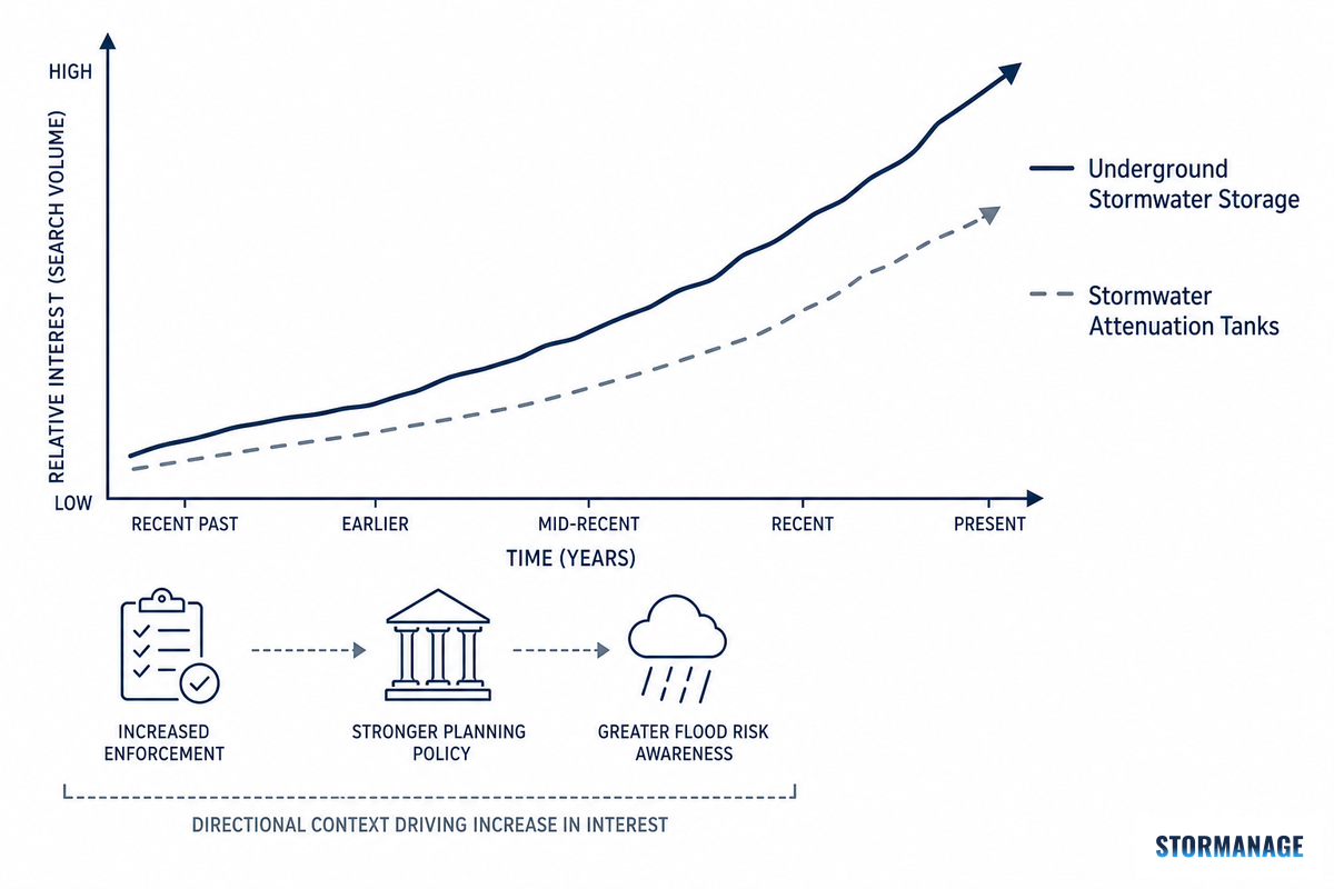
Two real developments on the regulatory front that are driving demand for underground stormwater storage, not away from it-both should affect your planning of a project’s budget and schedule into the future. First, on the regulatory side of things in the US, municipal enforcement is ramping up. Washington State’s proposed 2026 Construction Stormwater General Permit includes enhanced inspection requirements (certified inspector sign-off required for sites less than an acre) and numeric turbidity limits for discharges to impaired waters, while San Francisco’s Public Utilities Commission has set up a new fine-and-fee structure to enforce its Stormwater Management Ordinance (in effect July 2026). While neither would revise this guide’s sizing equation, they certainly increase the consequences for getting the design wrong and missing a compliance date; incorporate these increased inspection budget line items and schedules accordingly.
In the UK, the honest appraisal at present is that the country is moving toward greater uniformity of expectations for Sustainable Drainage Systems (SuDS), but it remains planning law rather than statutory code-Schedule 3 still hasn’t been commenced in England and the Defra’s National Standards published in June 2025 are advisory and require implementation through individual planning authorities rather than an overarching legislative mandate. Planning for a UK project for any time in 2027 and beyond? Look at your local planning authority’s progress on establishing a SuDS Approval Body, don’t bet on an English statutory mandate.
Those regulatory indications seem to align with what’s happening in the real world: search interest in “underground stormwater storage systems” is up by approximately 52% year-over-year, and in “stormwater attenuation tanks” (the UK-market term for underground systems) by roughly 50% – suggesting not just seasonal variability but a trend driven by increased enforcement and planning policy pressures. (While total stormwater market size estimates are available, they serve only as directional background here; we aren’t relying on any of them to predict the systems that can be installed or where.)
Frequently Asked Questions
Q: How deep can a stormwater detention tank be?
View Answer
There is no general maximum – cover depth for underground systems is primarily determined by site grade, the invert elevations of connected pipes, and the product’s cover depth ratings, rather than a set maximum. For example, one of the case studies presented in this guide included an underground storage tank that was buried 9.5 feet below the surface of a parking lot, a fairly common burial depth for a commercial development with typical utility conflicts. What does have limits, however, is the minimum cover. Most underground storage systems are designed with both a minimum cover depth, recommended by the manufacturer to prevent surface loads from being applied directly to the product structure, and a maximum cover depth, beyond which the structural capacity is no longer guaranteed – these specifications will be found on the product’s engineering documentation, not in a generic rule book.
Q: How long should a detention tank take to drain between storms?
View Answer
Most local authorities require a detention facility to completely empty out over a defined period following a storm – often between 24 to 72 hours, so that it is ready for the next storm. This drawdown time is not a design parameter that can be chosen at will, it’s a result of the outlet orifice design – and if your calculated drawdown time is higher than that required, then the orifice needs to be enlarged, which will then increase the peak discharge rate and potentially the storage volume calculation as well, therefore it must be evaluated during the sizing process rather than as an after thought.
Q: Do I need a separate water-quality volume in addition to the detention volume?
View Answer
In the majority of U.S. jurisdictions, yes. Under the same Stormwater Code, the water quality volume and the detention volume often represent two separate sizing criteria; the latter governs peak discharge rate and the former controls smaller, more frequent “first flush” storm events. This oversight of sizing only for detention volume and later receiving a correction at plan review for missing the water quality volume requirement is a very common, and expensive mistake made by engineers who have recently begun practicing in a new jurisdiction. Verify the requirement for both volume calculation from the appropriate local jurisdiction before proceeding.
Q: What software do engineers use to verify detention designs?
View Answer
The most common stormwater tools used to verify detention pond or tank size include EPA’s Storm Water Management Model (SWMM), which is more suitable for larger or hydraulically complicated sites, and the stormwater software HydroCAD. Both programs can develop a full hydrograph, unlike single peak-flow number calculation using the Rational Method as outlined earlier in this guide. That output lets engineers evaluate various storm durations to ensure that their selected “critical” storm duration from hand calculations truly controls design.
Q: What’s a typical orifice size for a small commercial site?
View Answer
Depends on the maximum permitted discharge rate for your site and the available head at the outlet – so no one standard figure to confidently mention here – a published example calculation for a smaller site (roughly 1 hectare, impervious) sized an outlet orifice at about 0.22 meters (roughly 8.7 inches) in diameter to hit its target discharge rate – at least gives you a feel for scale on a small commercial parcel. Your own number requires plugging in the allowable Q and available head for your project into the orifice equation – have your civil engineer provide that as a deliverable, don’t guess.
Q: Is an underground tank more expensive than a detention pond per cubic foot?
View Answer
Yes, to a large extent, on initial capital cost per cubic foot. Overall project economics is what really counts (see Land-Value Payback Test).
Our Perspective
Storm Manage has delivered 538+ SuDS & stormwater drainage schemes in the UK across 40 offices, spanning both terminology divide in the USA (detention), the UK (attenuation) & Australia (OSD) – and this is one reason we structured this as a methodology-focused guide rather than a purely product focused one. The principles & calculation of cost, risk & errors as discussed above apply whether or not you end up selecting one of our products or another manufacturer’s – you’ll find our site offers tools & data for project-specific numbers when the time is right.