We use the details you submit to review and respond to your project enquiry. Entries are handled in this website’s WordPress database using Fluent Forms; our hosting and email providers may process the submitted details. Other technical providers receive only the data described in our Privacy Policy.
Please do not send passwords, payment-card details, government identification numbers, sensitive personal data, or unnecessary confidential third-party information.
Applications by Sector Hub is a screening resource for finding relevant stormwater examples, not a final design rule. In regulated industrial scenarios, sector can pinpoint potential pollutants and corresponding permit requirements. Final hydraulic and structural selection still depends on site capacity, the necessary discharge function, and installation and maintenance procedures.
Applications by Sector Hub separates two decisions. Use sector to screen regulatory and pollutant risk; use six site constraints to select infiltration, attenuation, detention, OSD, harvesting, or a combined treatment train.
Quick Specs
Decision method: six site constraints, followed in a defined order
Use: concept screening and supplier brief preparation
Not a substitute for: hydraulic, geotechnical, structural, environmental, or regulatory design
Primary output: a defensible storage function and a list of missing evidence
Key points
Sector matters earlier than many selection guides admit, especially for industrial pollutant and permit screening.
Local numeric criteria may govern, but values from one jurisdiction shouldn’t be presented as universal thresholds.
Suppliers should receive a site brief, not just a sector label and an estimated tank size.
Where Sector Screening Ends and System Selection Begins
Sector screening can identify likely regulatory and pollutant risks during early project planning, but can’t select an end-state stormwater system. Hydraulic, structural, water quality, access, and approval decisions specific to the site must take precedence before storage configuration is proposed.
Compare two projects that share the same broad “commercial” category: an office park with shallow ground, light loading, and extra area for surface controls; and a service yard with hydrocarbons, utility corridors, restricted discharge, limited cover, and constrained access. Using the “commercial” category in both cases helps direct further inquiry, but design evidence still controls the technical decision.
The Sector-to-Function Boundary
This Sector-to-Function Boundary employs sector for preliminary risk evaluation, in conjunction with site evidence, to inform the selection of a stormwater storage configuration.
Do
Screen sector-linked pollutants and permit duties
Confirm site tests and discharge conditions
Define function before module configuration
Don’t
Copy a sector example without checking scope
Assume identical sites need identical wrapping
Treat a navigation label as an approval basis
The Six-Constraint Stormwater Compass
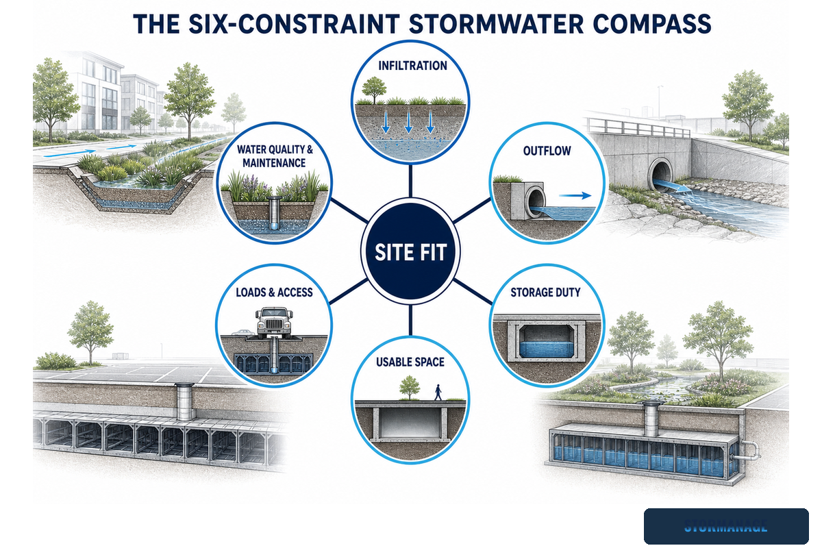
The Six-Constraint Stormwater Compass uses site evidence to guide initial system decisions through six checks: infiltration, outflow, storage duty, usable geometry, structural access, and water quality. Complete all six before a vendor or engineer proposes a commercially available configuration.
Six checks before system selection
The Six-Constraint Stormwater Compass provides a quick visual summary of six interconnected parameters. Current national SuDS standards for England likewise treat runoff destination, water quality, construction, operation, and maintenance as connected design responsibilities rather than isolated product choices.
Infiltration feasibility: field evidence, seasonal groundwater, contamination, sensitive receptors, and authority acceptance.
Permitted outflow: infiltration, controlled discharge, detention period, no-discharge condition, or a defined reuse demand.
Storage duty: catchment inputs, design event, runoff assumptions, drawdown objective, and required net volume.
Usable geometry: real footprint, formation level, utilities, cover, module height, clearances, and construction tolerance.
Structural and access conditions: surface use, permanent and construction loads, support, inspection openings, and maintenance route.
Water quality: sediment, hydrocarbons, debris, pretreatment, isolation, overflow, and responsibility after handover.
This method works because each step limits subsequent options. Poor infiltration test results can eliminate the option of infiltrative discharges. Utility limits can force a shift to off-site discharges. Restrictions on ground access can limit available stormwater storage options. In the end, the method delivers a reasoned shortlist, but doesn’t replace calculation or permitting.
Most often, project teams will calculate a stormwater design volume and then try to modify all downstream disciplines to match. In fact, the opposite logic should be followed. If catchment loading, groundwater, outflow, or access criteria can’t be accommodated, then the “calculated tank volume” is simply incomplete.
Can the Site Infiltrate Water Safely?
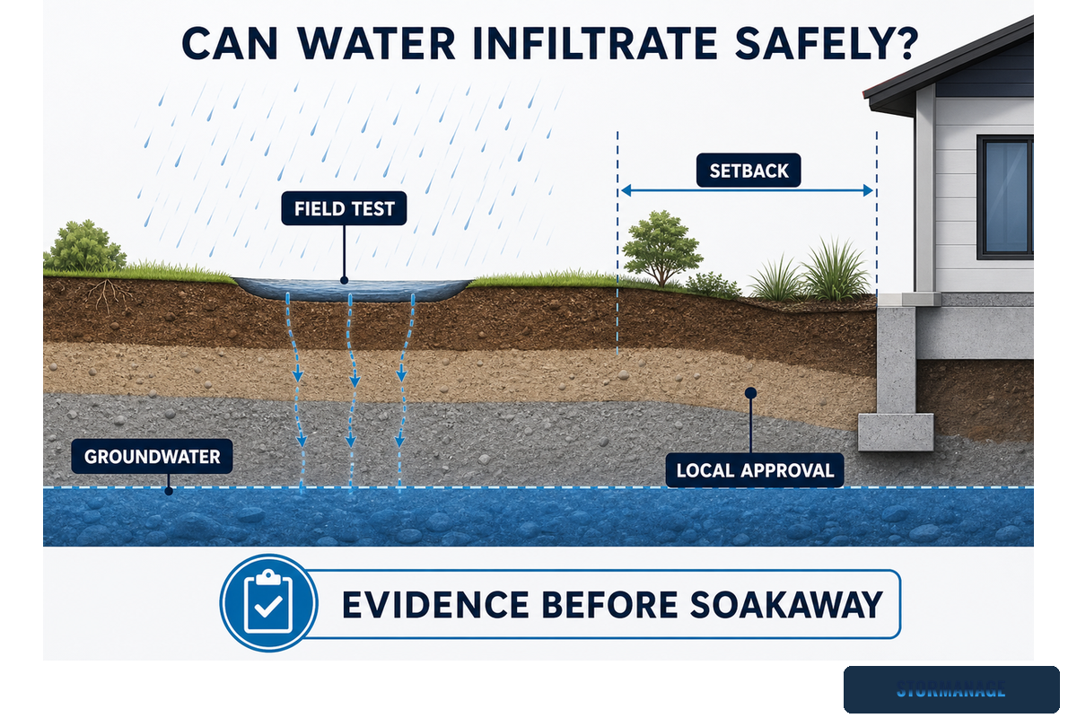
Infiltration can only be considered when field conditions, groundwater, chemical contamination and local authority guidelines all support it. Neither a large field area nor a standard soil type automatically makes a soakaway or infiltration basin feasible or permissible. Treat approval as a condition, not an assumption.
Guidelines like those developed in Massachusetts for shallow Class V wells highlight the evidence chain: soils and groundwater, contaminant source controls, pretreatment or filtration, spill control, and existing site conditions can all be relevant. The MassDEP shallow UIC guidance isn’t a generic design protocol, but it’s strong evidence that infiltration is a water-quality and regulatory decision as well as a hydraulic one.
Configuration for U.S. projects requires inspection too. Stormwater infiltration systems that use piping to distribute water below the surface can fall under the definition of a Class V stormwater drainage well. This classification is part of EPA’s decision table that highlights specific underground piping and manufactured subsurface structures. While not all surface infiltration systems may qualify, states can have additional requirements; as a result, the appropriate process depends on the permitting authority’s judgment.
Local numeric criteria may apply when the project location and scope match. Don’t transfer groundwater separation or infiltration-rate values from one drainage manual to another jurisdiction. Record the test method, locations, seasonal context, contamination review, and authority response. If evidence remains uncertain, keep infiltration out of the base design. For product context only, see Storm Manage’s soakaway crate overview after feasibility has been established.
A single unplanned pit trial isn’t enough reason to advance an infiltration facility. Groundwater, variability in infiltration rates, clogging potential, and runoff source characteristics might all overturn that initial impression.
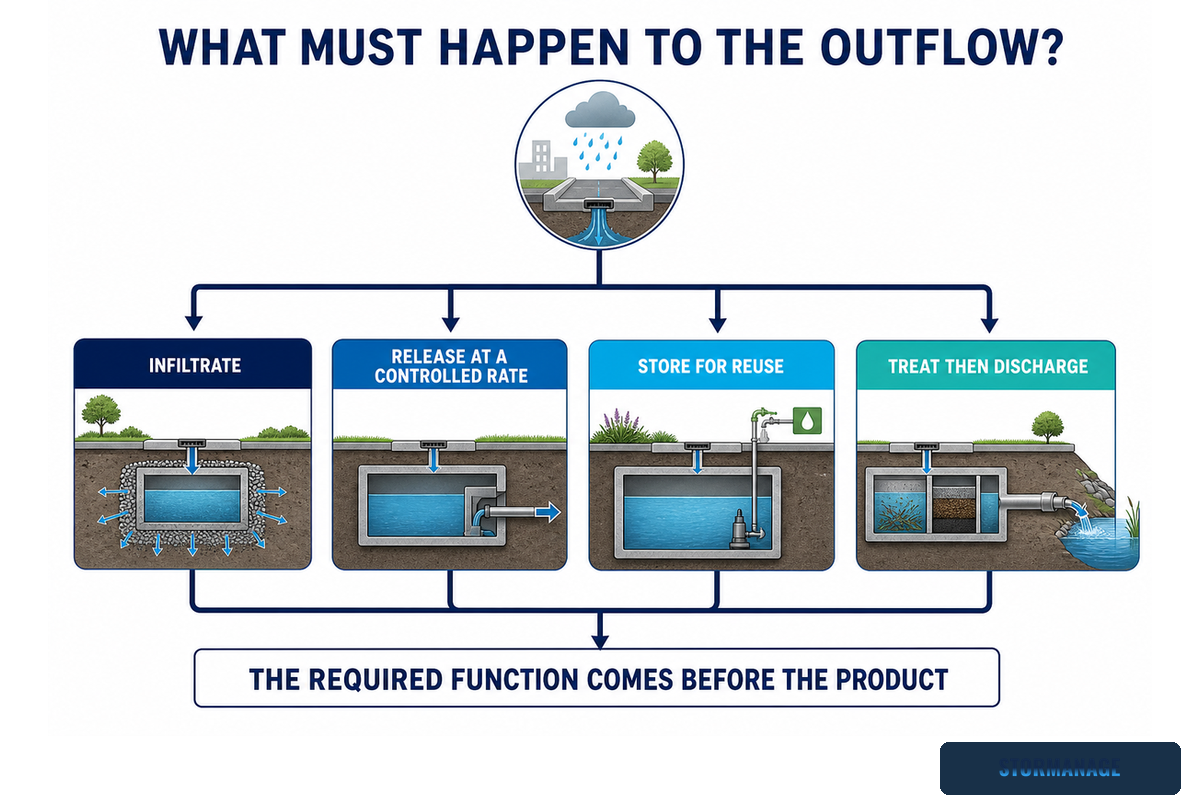
What Must Happen to the Outflow?
Outflow requirements define the storage function: water may infiltrate, leave through a restricted outlet, remain temporarily detained, or be held for a documented reuse demand. These outcomes change lining, outlet control, overflow, treatment, operating assumptions, and the evidence needed for approval.
Function is defined by the required water outcome
Outcome
Opening evidence
Configuration question
Infiltrate to ground
Field tests, groundwater, contamination, approval
How will water distribute and how will sediment be intercepted?
Restricted discharge
Allowable rate, receiving point, control basis
What lining, outlet, overflow, and drawdown arrangement is required?
Which local compliance and maintenance conditions control?
Rainwater reuse
Demand profile, quality requirement, backup and overflow
How will usable volume, treatment, and operating controls interact?
Attenuation, detention, and on-site detention aren’t interchangeable labels worldwide. Use the term defined by the governing drainage framework; for example, England’s national SuDS standards set a jurisdiction-specific runoff-destination hierarchy. Readers comparing implementation routes can use the separate attenuation tank, stormwater detention tank, and OSD tank pages only after the required water outcome is clear.
Common mistake: specifying “an unlined tank” before the authority has accepted infiltration. Wrapping is an output of the function and site evidence, not an aesthetic product choice.
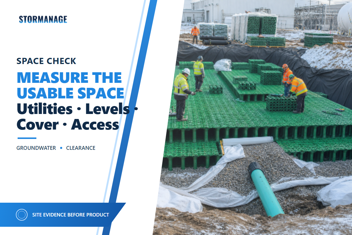
How Much Underground Space Is Actually Usable?
Usable underground space is the net buildable area after deducting utilities, formation level, groundwater, cover, access, clearances, and construction tolerances. It isn’t the overall site area, and it isn’t the required net storage volume. The remaining envelope, not the nominal footprint, governs layout.
Take a hypothetical rectangular area measuring 20 m by 10 m. At first glance, it offers 200 m² of plan area. Now remove a utility corridor along one side, keep an inspection route open, respect edge clearances, and account for construction working room. After those deductions, the footprint is smaller and less regular. This isn’t a sizing example: the hydraulic designer still needs catchment, rainfall, outflow, and storage calculations before net volume or dimensions can be set.
A short six-page modeling study is a useful reminder that storage-zone geometry and effective volume depend on the example’s rainfall, catchment, site geometry, and outlet assumptions. Those values describe one model, not a standard design ratio.
Separate three quantities in the project brief—required net storage, set by the hydraulic basis; gross modular envelope, set by the system choice and void arrangement; and excavation envelope, set by the gross envelope plus cover, bedding, wrapping, working room and construction access. For associated planning context, use the detention tank cost and sizing guide as a scoping tool, not as a substitute for project calculations.
Practical check: establish that after the landscaping or pavement is complete, the inspector and cleaning system can reach the inlet, outlet and sediment-control points. If not, the space isn’t fully available space.
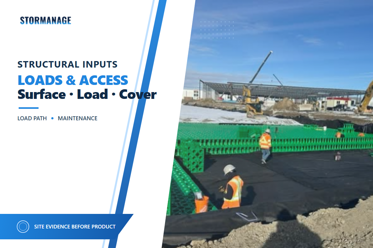
What Loads, Cover, and Access Conditions Will the System Face?
Structural screening begins with surface use, permanent and construction loading, cover, pavement build-up, formation support, lateral restraint, installation sequence and inspection access. No generic load class or module name can establish suitability without the whole project build-up. Each input must be documented before configuration is shortlisted.
A granted U.S. patent for a modular stormwater crate describes trusses, columns, side panels, stacking, deformation control, and resistance to backfill intrusion. That mechanism-level description helps explain why geometry, assembly, and installation are structurally connected. It doesn’t verify the capacity of another product or remove the need for project-specific checks. England’s national SuDS standards provide a separate authority example by requiring structural integrity, safe construction, operation, and maintenance to be addressed within the project scope.
A landscaped area, a car park and a service yard impose differing demands on the same buried footprint. Construction plant that’s temporary may govern before the final pavement is in. A shallow cover can magnify sensitivity to the build-up above. Poor formation or backfill control can invalidate a configuration that passed a clean calculation. Provide the load cases, construction stages, proposed cover, ground support, access openings and responsibility for installation controls.
Installation planning should sit alongside structural validation. Storm Manage’s soakaway crate installation guide can help frame sequencing questions, but the project-approved method statement controls.
Practitioner signal: civil engineering discussions often return to cover, compaction, groundwater, access routes, and sediment removal. These aren’t design criteria; they’re useful prompts for identifying oversights before construction.
What Pretreatment and Maintenance Access Are Required?
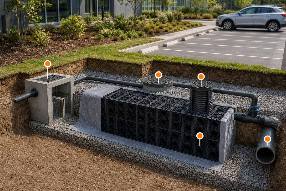
Pretreatment and maintenance must be designed around the catchment risk, sediment load, hydrocarbons, debris, inlet and outlet access, isolation approach, overflow route and nominated maintenance owner. These are fundamental system inputs because underground storage may conceal problems until capacity or water quality has already suffered.
The Minnesota Stormwater Manual states that constituent fate hinges on constituent type and magnitude, runoff volume, practice type and subsurface conditions. It notes that more mobile pollutants such as chloride aren’t reliably removed by typical infiltration media. So a soil label can’t determine treatment performance.
Specify what should be intercepted upstream, the points where sediment can settle, how the storage structure can be isolated, and what points can be inspected by camera or direct access. Then specify the trigger for cleaning. A standard calendar interval is less defensible than an inspection-based schedule associated with the catchment and system. The MassDEP shallow UIC guidance provides one authority example linking contaminant controls, pretreatment, spill control, and site conditions. Cover material must also be protected during installation and service; work out what duties geotextile and geomembrane have to perform based on the hydraulic function and ground conditions.
Maintenance access can be a formal requirement rather than an optional detail. One municipal code requires underground storage to allow easy access and correction of identified defects. Because the legal wording is local, the transferable project lesson is narrower: if the brief omits access, responsibility, and corrective action, the maintenance plan is incomplete.
Common error: placing inspection openings where parked cars, permanent features, or finished landscaping will obstruct access later. Examine the maintenance route on the final site plan, not only on the drainage drawings.
When Surface Measures and Underground Storage Work Together
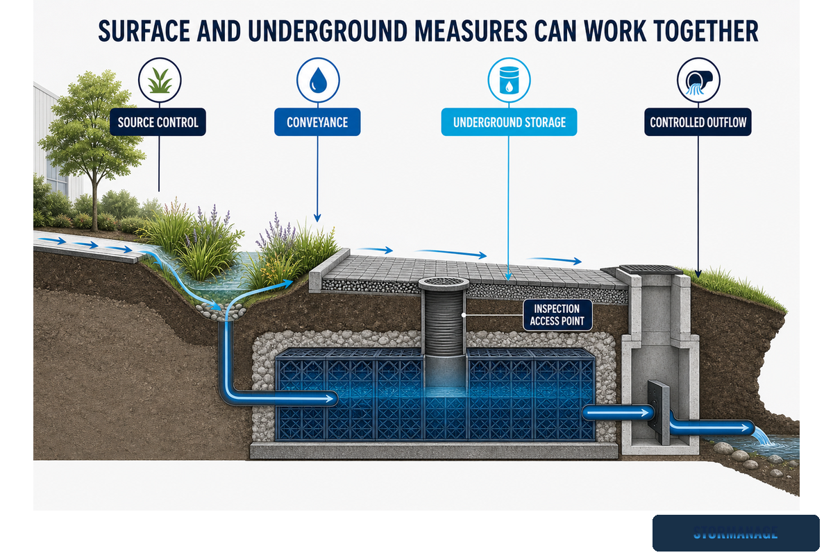
Surface features and underground storage can occupy successive zones of a single integrated Sustainable Drainage System (SuDS) sequence. Surface elements like swales, rain gardens, bioswales, and permeable surfaces delay, filter, or disconnect flows, while the remaining quantity is managed with storage.
This can address constrained conditions like limited yard space, a target release rate or controlled discharge at a specific time, or groundwater limitations.
Since surface ponds weren’t practical for the zero-lot-line site, a conventional drainage approach using a vault-style subterranean storage tank was paired with upstream pretreatment, permeable surfaces, swales, trench drains, groundwater separation, controlled discharge, and an operation-and-maintenance plan. This example doesn’t prove that the combination is best for every context, but it shows how distributed surface and buried functions can be matched to available land, flow quantities, treatment needs, and release parameters.
“With surface ponds off the table, the strategy shifted entirely to subsurface solutions.”
England’s 2025 national SuDS standards provide current authority context for new infrastructure and development in England. They aren’t a universal numeric standard. Although not designed for retrofit SuDS, the document says they may serve as a starting point where project constraints allow. For U.S.-focused terminology and compliance context, see Storm Manage’s LID and EPA BMP compliance guide.
Decision point: Choose a dual-function setup only when each element has a specific job, not because adding more devices makes the design appear more complete.
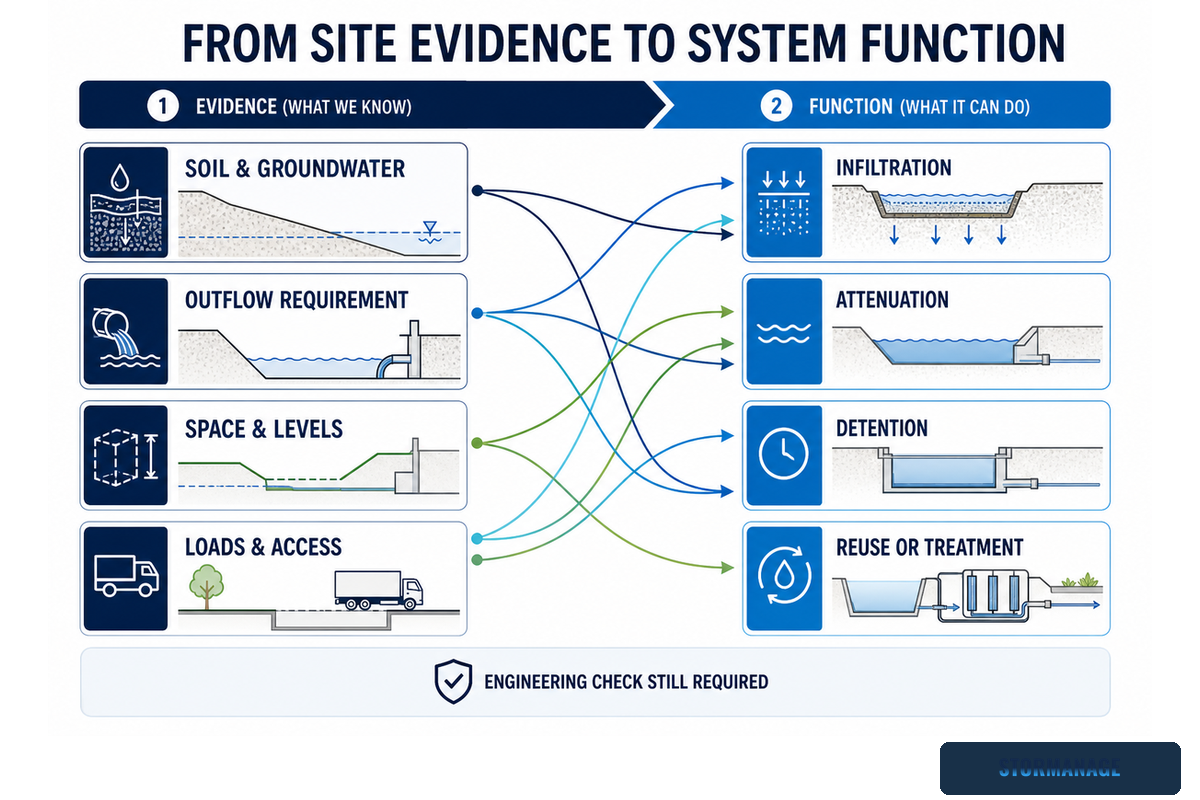
From Site Evidence to System Function
A function table can convert site observations into a structured check, but it can’t replace analysis or detailed design. Its role is to show plausible configurations, missing information, and questions for the design team. The national SuDS standards for England offer one authority example of why runoff destination, water quality, construction, operation, and maintenance must remain connected.
How is water distributed without unintended bypass?
What prevents sediment and harmful pollutants entering?
Unresolved contamination, groundwater, or Class V status
Restricted release
Permitted rate, event basis, outlet and overflow
Attenuation storage
Which lining and flow-control arrangement applies?
Can the control and sediment points be reached?
No confirmed receiving point or discharge consent
Temporary detention
Local definition, duration, discharge, drawdown
Detention or OSD role
How do controls match the local framework?
Who inspects and restores capacity?
Generic terminology without jurisdictional criteria
Supply a reuse demand
Demand profile, quality, backup, overflow
Harvesting or dual-duty storage
How is usable water separated and controlled?
What treatment and operating checks apply?
No defined demand or water-quality basis
High-load surface
Load cases, cover, pavement, formation, staging
Structurally checked buried storage
Does the build-up match the checked configuration?
Where can inspection openings remain accessible?
Unverified construction or permanent loading
Pollutant-risk catchment
Source profile, treatment train, spill response
Isolated or pretreated storage
Must infiltration be excluded or isolated?
How is captured material removed safely?
No contaminant or maintenance-control plan
Constrained footprint
Utilities, levels, clearances, access, construction route
Geometry-led modular arrangement
Can the required duty fit the net envelope?
Can controls be reached after completion?
Nominal area used without net-envelope proof
Combined treatment and quantity control
Whole-train performance and exceedance route
Surface plus underground arrangement
Where does each stage discharge?
Which stage captures and exposes maintenance risk?
Components added without distinct functions
Once functions and constraints are characterized, use Storm Manage’s Applications by Sector Hub to see how these factors appear in typical site settings. Use the hub to confirm context, not to override the evidence already gathered.
Stop condition: If a row in the table can’t be completed without guessing, the next activity is additional data collection, not product selection.
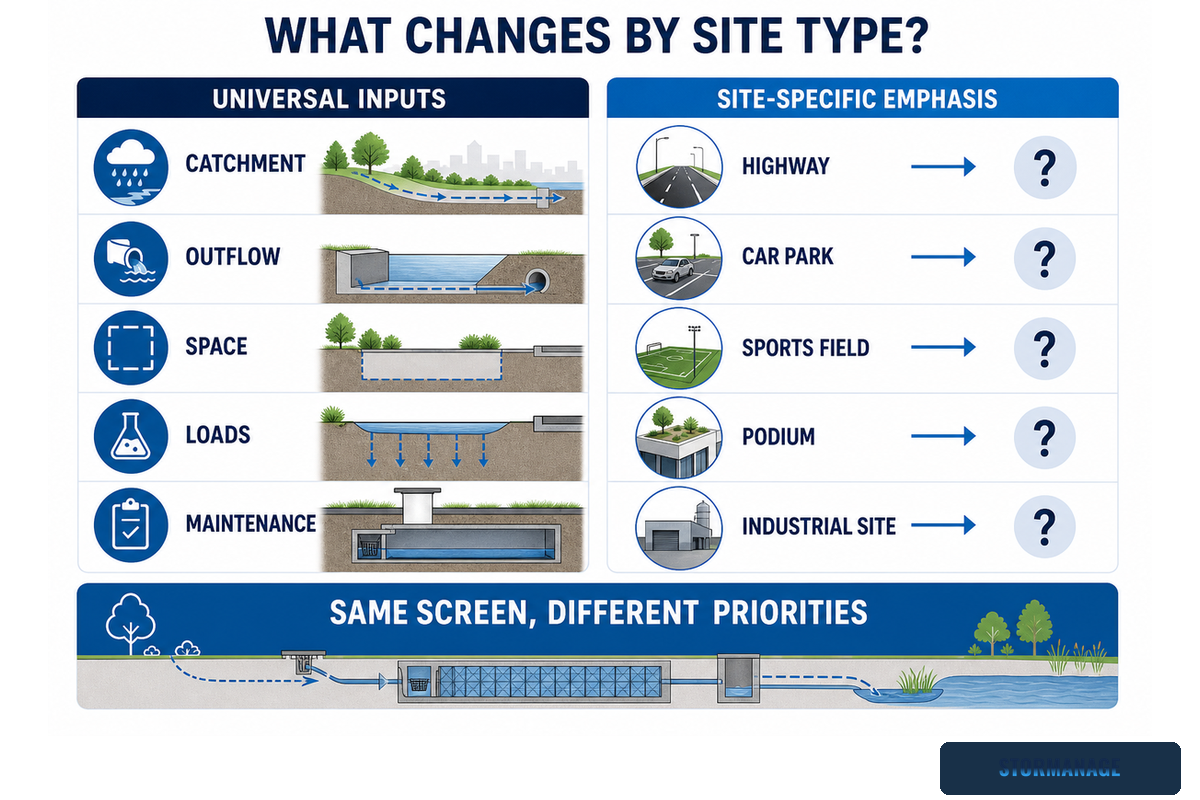
Which Inputs Change by Site Type, and Which Stay Universal?
Site type shapes, but doesn’t eliminate, considerations for pollution hazards, pollutant loading, space constraints, access, approvals, and structural or hydraulic design. Universal checks still include infiltration feasibility, outflow, storage duty, usable geometry, load cases, water quality, maintenance access, and local authorization.
Four categories of variables are worth tracking. First, the runoff contamination profile influences treatment and infiltration acceptability. EPA’s industrial stormwater fact sheets show how typical pollutants and candidate controls can vary from one regulated sector to another.
Second, the site’s typical use influences permanent loads, construction access, and maintenance constraints. Third, utilities, staging areas, and final grades define the buildable footprint. Fourth, ownership and approval routes influence ongoing maintenance accountability and document-retention requirements.
What’s invariant? Screen sector-linked obligations, define what must happen to the water, test the site, establish usable geometry, check loads and access, and close the water-quality and maintenance loop. This is the Sector-to-Function Boundary in practice.
Many project teams assume that a prior project is a valid template because its sector and module family match. Reuse the checklist and evidence format, but don’t reuse an unchecked configuration.
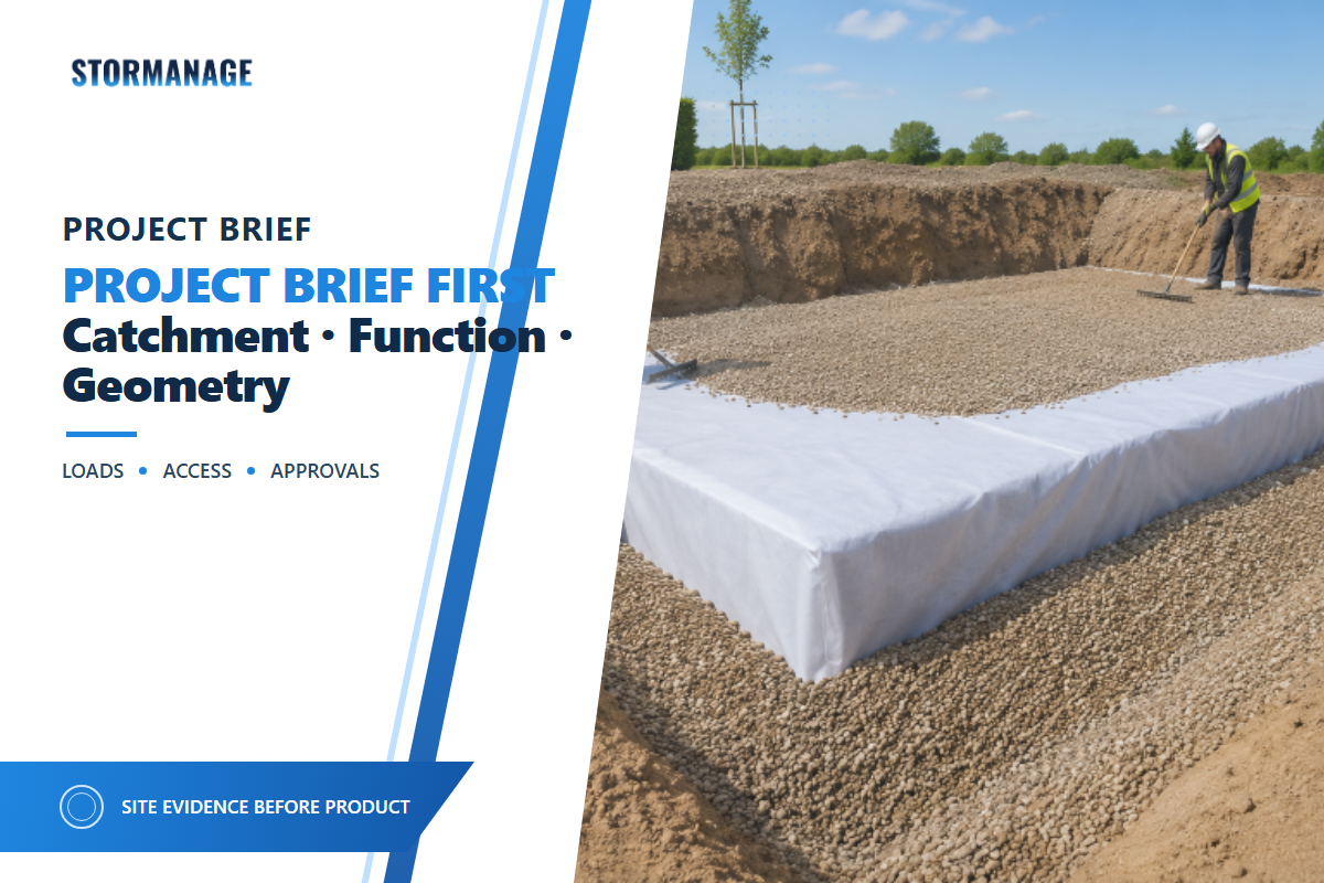
Build the Project Brief Before Asking for a Recommendation
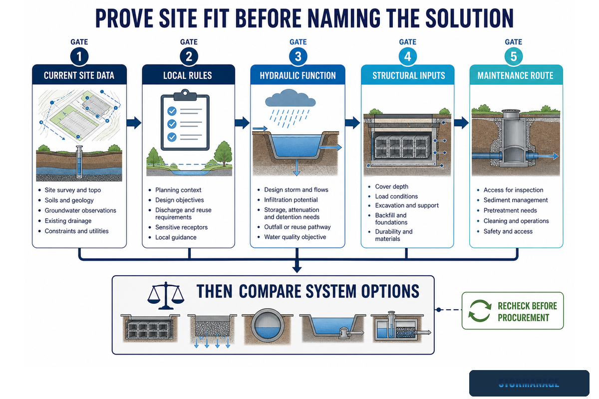
A supplier brief needs the authority basis, catchment and hydraulic inputs, functional requirements, usable geometry, loads, treatment, maintenance access, programme, and logistics constraints. It should separate known facts from assumptions that the next stage must confirm.
Define the authority basis: record the location, drainage framework, sector-linked duties, and the reviewer or permitting authority.
State the water outcome: document catchment inputs, design event, net storage duty, permitted discharge, infiltration evidence, reuse demand, and overflow.
Freeze the buildable envelope: show footprint, formation level, depth, cover, utilities, surface use, access, and construction constraints.
Close quality and maintenance gaps: specify inlet, outlet, pretreatment, lining, isolation, inspection, cleaning, and responsibility.
For U.S. infiltration projects, also request details about piping and distribution, and check whether the proposed configuration triggers UIC Class V review. Assigning “confirmed”, “provisional”, “supplier input”, or “authority approval” to each field helps prevent unstated assumptions.
200,000 m²+reported production base
≈50,000 m³reported monthly output
3–10 daysusual stated lead time
Up to 330 m³installed volume per optimized 40HQ
The figures above are Storm Manage first-party operating data supplied for this project, not independent industry benchmarks. Storm Manage also reports annual production capacity above 600,000 m³, 200+ injection-moulding machines, 12+ mould sets, technical drawings, matching accessories, container-loading support, and OEM/ODM cooperation. Confirm project-specific availability in the quotation.
Procurement checklist: ask the supplier to return a marked-up brief showing which inputs were accepted, which remain unresolved, and which evidence or interfaces fall outside its response. A documented handoff is more useful than a recommendation built on unstated assumptions.
The 2026 Direction: Prove Site Fit Before Naming a Sector Solution
For current stormwater procurement, verify local rules, project scope, site testing, supplier evidence, and documents before making a recommendation. Market-growth numbers alone don’t establish adoption, and a standard for one region isn’t an international rule.
Regulatory specificity is the practical signal, not a generic market-growth claim. England published revised national SuDS standards on 19 June 2025 for new infrastructure and development in England; the document says retrofit projects may use them as a starting point even though some requirements may not be directly applicable. U.S. EPA pages separately distinguish industrial-sector screening and Class V configurations. Australian on-site detention projects may face their own council criteria; Storm Manage’s NSW council OSD compliance overview provides starting terminology, while current council requirements remain authoritative.
For a July 2026 project, tag the authority references and site information on which the decision was based with their respective dates. Revalidate them if the project timetable changes. Check whether local standards have changed, whether the project is new development or retrofit, and whether a numeric criterion genuinely applies to this location and asset.
Key takeaway
Sector can start the risk screen, but current site evidence and the required water function must finish system selection.
Can another engineer track every major decision back to a current authority standard, field observation, or explicitly stated assumption? If not, the recommendation isn’t ready for procurement.
Frequently Asked Questions
What does “Applications by Sector Hub” mean for a stormwater project?
Answer
Applications by Sector Hub groups project settings and, in some regulated industrial contexts, supports pollutant and permit screening. EPA’s industrial stormwater fact sheets are one jurisdiction-specific example. The hub isn’t a complete design rule: infiltration, outflow, storage duty, usable geometry, loading and access, water quality, and maintenance still control the engineering route and the evidence required before configuration.
How do I choose between a soakaway and an attenuation tank?
Answer
Start with where runoff is allowed to go. A soakaway requires acceptable infiltration, groundwater, contamination, and approval evidence. An attenuation tank stores runoff and releases it through a controlled outlet. Storage, drawdown, overflow, pretreatment, lining, access, maintenance responsibility, and local requirements still need project-specific design before either route can be selected.
Can the same underground stormwater system be used in different sectors?
Answer
The same geocellular platform may appear in several sectors, but the completed configuration isn’t automatically transferable. Wrapping, module layout, cover, structural context, inlet and outlet controls, pretreatment, overflow, inspection access, and maintenance ownership can all change. A product family can be shared while the hydraulic and structural design remains project-specific. Reuse the decision method, not an unchecked configuration.
What information is needed before sizing underground stormwater storage?
Answer
Provide the site location and authority, drainage criteria, catchment, design event, runoff assumptions, permitted discharge, infiltration evidence, usable footprint and depth, cover and loading, inlet and outlet details, overflow, pretreatment, maintenance access, and any reuse demand. Mark each input as confirmed or provisional. If the project uses subsurface infiltration in the United States, also ask whether the configuration needs UIC Class V review. These inputs let a qualified designer establish storage duty and expose missing evidence before procurement.
Can underground storage be combined with SuDS, LID, or WSUD measures?
Answer
Yes, when each component has a defined job and the whole arrangement is checked as one treatment train. Surface measures may slow, treat, infiltrate, or disconnect runoff. Underground storage may then manage residual quantity, a restricted discharge, or a defined reuse requirement. A continuous flow path, an exceedance route, treatment assumptions, accessible maintenance points, and jurisdiction-specific approval are still needed. Designers should also state what happens when a surface component is bypassed, saturated, or temporarily unavailable, and who restores its function. Combining measures isn’t automatically better: a component that adds no distinct hydraulic or water-quality duty can add construction interfaces, inspection burden, and maintenance risk without improving the outcome.
Bring evidence, not just a sector label
Send Storm Manage your authority basis, storage duty, usable geometry, loading, treatment, access, and logistics constraints. Storm Manage’s team can review the brief, identify missing inputs, and coordinate drawings, accessories, and container planning around a defined project role.
This guide combines current government and municipal sources, a short academic modeling example, a practitioner discussion, a project-specific engineering case, and Storm Manage first-party operating data. Jurisdiction-specific criteria are labeled and aren’t presented as universal design values. Hypothetical scenarios illustrate the method and aren’t completed project results.
Storm Manage develops project-ready modular underground storage systems with technical drawings, matching accessories, container-loading support, and OEM/ODM cooperation for overseas civil-engineering and drainage work.