Attenuation Tank Design & Installation: Geocellular Systems Engineered to Your Discharge Rate

Whether your design and installation of attenuation tanks is a success or failure depends on a single number – the rate your Lead Local Flood Authority will let you discharge at. Storm Manage design and build geocellular attenuation tanks based around that figure – 95% void ratio crates, sized to a controlled discharge rate, sealed WATERTIGHT, and designed to pass an LLFA inspection and be adopted. We make the components and produce the drawings, not just the crates.

Request Design Support & a Quote
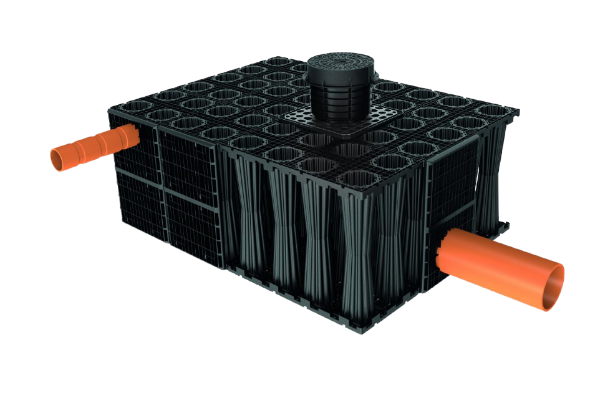
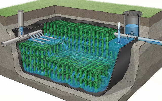
Geocellular attenuation tank design and installation system

StormGrid Attenuation System, at a glance

  • 95% void ratio (effective storage per m³ excavated)
  • 20–60 t/m² nominal load grades, SG-E20 to SG-H60
  • 190 / 237.5 L per module, H400 / H500 heights
  • 50 yr design service life, buried
  • CIRIA C737 structural design reference (current)
  • 400+ / 30+ projects delivered / countries

Why Attenuation Design Starts With Your Discharge Rate, Not the Tank

[01] SYSTEM LOGIC

Many attenuation tank designs are based on designing the tank and then failing at the planning submission because the reviewer look from the other direction, based on their permitted outflow rate not the crates you found appealing. The reason is that an attenuation tank simply holds back the surface water from a storm until it can be slowly released through a flow control, so the storage you need is determined by how much you can discharge, not what the catalogue offer.

[02] MECHANISM

An attenuation tank temporarily stores stormwater runoff and releases it at a controlled rate to a sewer or watercourse. Its required storage volume is set by your permitted discharge rate, the design rainfall (with a climate change allowance), and the catchment’s impermeable area. Heavy rainfall on a developed site drive up peak flow rates and the risk of flooding downstream, which is why local authorities now require managing stormwater on new schemes. An attenuation tank is the part of that stormwater management strategy that buys time, it holds surface runoff and rainwater back and meters it out, so the storm drain and wider drainage network aren’t overwhelmed and localised flooding is avoided.

[03] INTEGRATION

It’s also important to be clear about what the design should achieve. A modular buried tank is a part of a SuDS management strategy not the drainage strategy as a whole; 2025 national standards want the attenuation to fit into the wider strategy with other surface water features such as swales, ponds, permeable surfaces and we work to ensure that the crate tank design integrates with this strategy and clearly identify where they’re the right solution.

Attenuation Tank Design: Sizing to a Controlled Discharge Rate

Sizing is a sequential process, not just a table. We refer to this as The Discharge-to-Storage Sizing Ladder, which consists of five steps that result in a justifiable number of crates required. This provides you with a method you can repeat rather than simply copy values into a planning document.

“We size every tank to the outflow first. Nine times out of ten a scheme that gets bounced at review was drawn to a round number of crates and never reconciled against the greenfield rate, so the storage was short before anyone put a spade in the ground.”

Storm Manage Engineering Team

Why a generic rate is not enough

the common mistake is sizing to a rule of thumb like “2–8 litres per second per hectare” — a useful first sanity check, but a real risk of a failed plan review, because your actual permitted rate is catchment-specific and set through the Environment Agency method and the LLFA. Storm Manage engineers build the tank to that number, not the rule of thumb.

01 Determine the allowable discharge rate.
this should be either the greenfield runoff for the site calculated using one of the Environment Agency methods (IH124 or FEH), or the figure supplied by your Lead Local Flood Authority. No allowance is added to the greenfield run-off rate.
02 Define the design storms and rainfall.
under the 2025 national standards, you need to manage runoff from 50% AEP (1 in 2) and 1% AEP (1 in 100) storms, incorporating the Environment Agency upper-end climate change allowance applicable to your catchment and epoch, and also the allowance for urban creep.
03 Calculate the necessary storage volume.
Model the design storms against the permitted discharge rate for a critical storm duration. The volume of water that can’t be released is the storage required. Most hydraulics design software (e.g. Causeway Flow, Autodesk InfoDrainage or MicroDrainage) will calculate this.
04 Translate storage into module counts.
Divide the total storage required by the storage capacity of each module; this will be the module nominal volume multiplied by the 95% void ratio, effectively using nearly all the box for storage.
05 Check depth, footprint and load.
Confirm the layout fits the plan area and cover depth available, and that the load grade suits the surface above (Rung applies back into H2-3 and H2-5).
Want the maths behind your project? Use our attenuation sizing calculator to convert area, rainfall and discharge into a StormGrid crate count — or request a StormGrid spec sheet.

StormGrid Geocellular Tanks for Attenuation: Load Classes & Heights

Attenuation buyers are told to “compare crates,” then handed catalogues with no numbers. We publish the full StormGrid table so your structural engineer can check it against CIRIA C737 before you order – the specification that actually governs whether a modular tank survives its design life is the structural one, not the marketing one. Structural adequacy is part of what the 2025 national standards expect a design to demonstrate.

Nominal load grades; 1 t/m² ≈ 9.81 kN/m². Vertical test loading, not an EN 124 cover class — confirm site-specific structural design to CIRIA C737.

Two heights, one selection logic

Every grade is offered in two height configurations so you tune excavation depth against storage density. H400 (1000x500x400mm, 190L) reduces the dig where cover is tight; H500 (1000x500x500mm, 237.5L) gives more storage per unit footprint where plan area is the constraint. The void ratio stays at 95% across every configuration.

The honest version other datasheets skip: Storm Manage won’t claim the widest load envelope on the market – Polystorm publishes a higher top grade, and we say so. What this range matches is the 95% void ratio that drives your crate count, and what it adds is a full spec table plus manufacturer-direct supply and third-party test reports, so procurement can vet the product on evidence rather than a datasheet slogan.

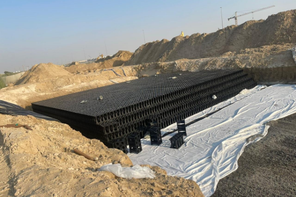
StormGrid Geocellular Tank Load Specifications
Model Grade Nominal load ≈ kN/m² Material Typical use above tank
SG-E20 Eco Light 20 20 t/m² ≈196 Recycled PP Landscape, gardens, non-trafficked
SG-L30 Light Standard 30 30 t/m² ≈294 Recycled PP Pedestrian paths, low-load public areas
SG-M40 Medium Duty 40 40 t/m² ≈392 Recycled PP Commercial yards, light parking
SG-H60 Heavy Duty 60 60 t/m² ≈588 100% Virgin PP Trafficked parking, access roads, industrial
SG-Custom Custom project-specific (to ≈65 t/m²) By design Highway margins, heavy plant, OEM/ODM
System Void ratio Stated load range Module Design life
Storm Manage StormGrid 95% 20–60 t/m² (≈65 custom) 1000×500×400 / 500 mm 50 years
Polypipe Polystorm 95% 20–83 t/m² modular cell 60+ years (mfr stated)
Wavin AquaCell (range) 94–96% product-dependent 1200×600×400 mm mfr stated

Impermeable Build-Up: Geomembrane vs Geotextile Wrap

The single most common specification error is wrapping an attenuation tank like a soakaway — an error the drainage hierarchy in the 2025 national SuDS standards is written to prevent. The wrap decides what the tank does, and getting it wrong turns a store-and-release tank into a leaking pit or a soakaway that won’t drain.

For attenuation (store-and-release), the crates are wrapped in an impermeable geomembrane with a protective geotextile fleece so the tank holds water and discharges only through the flow control. For a soakaway (infiltration), the crates are wrapped in a permeable geotextile only, so water passes into the surrounding ground.

Attenuation Tank Wrap Specification

Because an attenuation tank must be watertight, the membrane seams matter as much as the crate. The geomembrane and fleece ship with the modules, and the build specifies wedge-welded, air-tested joints (see the installation sequence below) so the tank is verified sealed before it’s buried.

The honest version other suppliers skip: this is a trade-off you can’t reverse once the tank is backfilled. Unlike a box-only supplier, Storm Manage engineers confirm the application – attenuation or infiltration – against your discharge consent before specifying the membrane, because the wrong wrap is the mistake that turn a compliant design into a site failure.

Attenuation Tank

Wrap Impermeable geomembrane + protective geotextile
Water Path Held, released via flow control at permitted rate
Ground Condition Any — including low-permeability clay

Soakaway / Infiltration

Wrap Permeable geotextile only
Water Path Infiltrates into surrounding soil
Ground Condition Needs adequate infiltration rate (BRE 365 test)

Attenuation Tank Installation: Excavation, Wrap, Build & Backfill Sequence

Installation is where an over-the-phone crate order goes wrong on site. The Watertight Build-Up Sequence below is the order of operations we detail on every StormGrid shop drawing, because the tank’s load rating and watertightness are earned during backfill, not printed on the box.

[PREP]
Excavate and prepare the formation. Dig to the design dimensions, hold a 45° angle of repose away from foundations, and lay and compact a granular base to a level formation.
[PREP]
Line the base. Roll out protective geotextile, then the impermeable geomembrane, extending both well beyond the tank footprint so they can be brought up and over.
[01]
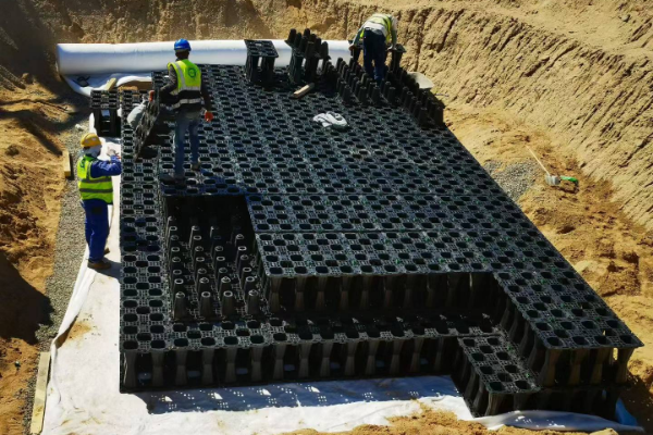
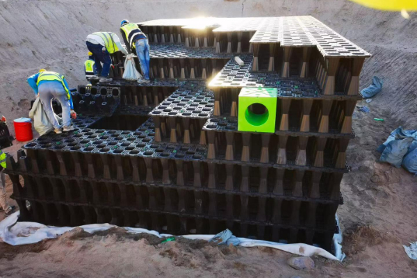
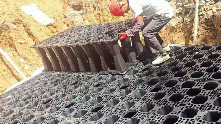
1. Crate the tank Assemble the StormGrid modules in accordance with the layout drawing, laying them square, to provide even load distribution.
[02]
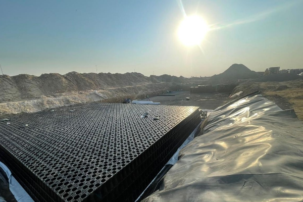
2. Seal it Up Drape the geomembrane over the crate and heat-weld/wedge weld the joints and top edges, then air test the geomembrane tank.
[03]
3. Pipe penetrations Add in the inlet, outlet and vents and seal the pipe penetrations to ensure that only flow passing through the flow control can enter or exit the tank.
[04]
4. Backfill the tank Place well-graded granular material in compacted layers around the crate up to the specified load class. Place cover to suit site use.
StormGrid Tank Installation and Backfill

Cover depth follows the load above

The cover depth isn’t fixed at one size – it’s defined by the weight passing over the tank and the class of crate below it. A basic 250mm cover is generally the minimum in a pedestrian area but is completely insufficient if the tank will be subjected to HGV loads where more cover and a heavier crate are required together with an engineered granular fill material surrounding the crate. It’s not a simple ‘this for that’ rule, even within the 250mm minimum. CIRIA C737 contains more guidance and clearly shows how cover depths vary – particularly with depth where increased overburden significantly influences the wheel load capacity and so cover depth is specified individually for each project, in line with the design expectations of the 2025 national SuDS standards.

The crate carries its load not in its base or walls but through bearing in the ground. That is why Storm Manage engineers specify cover depth per application to CIRIA C737 — production supplies the matching granular surround and, for a trafficked tank, a heavier SG-H60 grade, all sized to your wheel loads. Get that step wrong and the first car to drive over voids the load rating, deflecting the surface down into the tank.

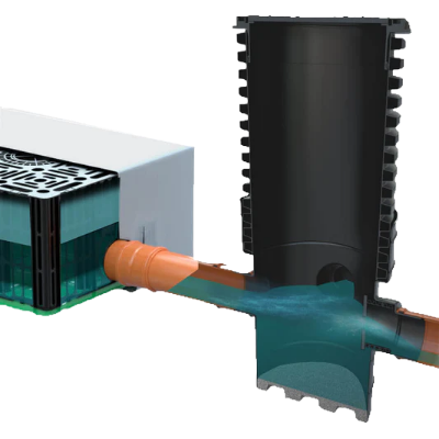
Flow Control Design and Outlet Chamber Layout

Flow Control Design: Orifice Plates, Vortex Controls & Outlet Chambers

4. Inlet, outlet and vents the device. This component is responsible for limiting outflow to the permitted discharge rate, and often attracts the most attention from reviewers of tank design and specification. The flow control is housed in an outlet chamber, and can take many forms – from simple orifice plates to more sophisticated vortex flow control devices (such as a Hydro-Brake), and will be sized so that the tank captures peak flows and then releases only at the specified approved rate.

Design Constraint: Blockage

Blockage is a design issue, not a detail. At low permitted rates the required opening can be small, and the 2025 standards call out small orifices (under roughly 50 mm) as needing positive protection from blockage. A vortex control has no small orifice to clog and is largely self-cleansing, so it is often the safer choice at tight discharge rates; whichever is used, the outlet chamber must give maintenance access.

Storm Manage’s design will match your approved rate to the selected flow control, and will also detail the outlet chamber to include appropriate rodding and inspection access so the flow control continues to operate as designed for its lifespan rather than blocking up with sediment after the first few months of use.

Other suppliers ship the crates and leave you to design the hydraulic performance and associated outlets for your stormwater attenuation system, so why leave room for error and over-protect the orifice at your risk? We specify and design everything to match your exact needs.

Designing for Adoption: 2025 SuDS Standards, CIRIA C753/C737/C768 & Maintenance

When complying with regulations for a stormwater attenuation tank it isn’t a single simple document. It’s a combination of up to four, comprising three from CIRIA and one from National House Building Council, so if your specification references an out of date document it can quickly appear ‘old hat’.

Purpose Current reference Superseded / legacy
Surface-water design, hierarchy, sizing CIRIA C753 (The SuDS Manual, 2015) + 2025 National Standards for SuDS (England) CIRIA C697:2007 — still cited by many design spreadsheets
Structural design of the modular tank CIRIA C737:2018 CIRIA C680 (2008) — the historical production basis
Construction of SuDS on site CIRIA C768

A note on our own paperwork: Storm Manage has a history of designing to CIRIA C680 and our vertical-load test report is to that basis. CIRIA C680 has since been updated to C737, so please direct your structural engineer to C737 as the design standard and provide our test data to support this. We would much rather flag this than allow an outdated standard number to appear on a submission unnoticed.

Attenuation Tank Standards and Maintenance

Adoption reality — worth knowing early: many water and sewerage companies decline to adopt geocellular tanks used purely for attenuation — United Utilities’ developer guidance, for example, states it will not adopt tanks provided solely for attenuation. Adoption policy is set company by company under the Sewerage Sector Guidance, so these tanks typically remain privately owned and maintained. That makes designed-in inspection and maintenance access essential, not optional.

Approval pathway varies by nation

In England this requires planning approval and the LLFA; against the 2025 non-statutory national standards. In Wales, sustainable drainage is statutory via Schedule 3 of the Flood and Water Management Act 2010, subject to approval from a SuDS Approval Body (SAB). In Scotland SEPA and Sewers for Scotland are relevant. Rather than a one-size-fits-all UK-wide package, we provide the appropriate specification, test report and stamped drawings that fit your particular location.

ISO 9001:2015
ISO 14001:2015
ISO 45001:2018
CE / BS EN accessory reports
SGS compression test
CIRIA C680 vertical-load test

Common Attenuation Design & Install Mistakes That Fail Plan Review

The failures that make it to the engineers’ desks, and occasionally to court, almost never involve a bad crate. The failures typically result from a shortcut in design or installation. One particularly sobering, and well-documented, example came in an ASCE report on underground plastic detention systems. It discussed a polypropylene tank under a car park that deformed and failed within four months of its installation, caused by thermoplastic creep that the specification hadn’t foreseen.

Mistake
Why It Fails
How We Avoid It
Ignoring long-term creep & loading
PP deforms under sustained/repeated load if under-designed
Structural design to CIRIA C737 (factor of safety, creep, cover); Virgin PP for heavy grades
Storage sized without climate allowance
Tank fills and surcharges in the design storm
Size to 50% + 1% AEP with current EA upper-end allowance + urban creep
Wrong wrap (geotextile on an attenuation tank)
Tank leaks; discharge not controlled
Impermeable geomembrane + fleece, wedge-welded, air-tested
Insufficient cover for the load class
Voids the load rating; surface deformation
Cover depth by grade to C737, engineered granular surround
No maintenance / inspection access
Silt reduces storage; outlet blocks
Silt trap upstream + inspection ports + jettable outlet chamber

The pattern remains the same. It’s usually a manufacturer who ship a box and then leaves the structural considerations up to somebody else. With Storm Manage, we supply the structural base design and shop drawings with our modules so that creep, surcharge, and other design decisions are made before your tank is ever buried.

Storm Manage Underground Stormwater Storage Manufacturer Facility

Manufacturer-Direct Supply: Specs, Shop Drawings, Lead Time & FOB

Buying attenuation crates through a merchant adds to the cost without adding any expertise. As the injection-moulding manufacturer, Storm Manage gives you direct access to the factory producing the modules and holding the relevant test data, produced under an ISO 9001 quality system. The matching accessories, technical drawings, and container-loading assistance will all be on the same order.

To compare costs on a like-for-like basis with concrete and pipe options, get a breakdown per cubic metre from our guide on attenuation tank costs. This page is dedicated to helping you get the design and the installation right, leaving the maths to the cost calculator.

What drives your delivered cost / programme | How it works with Storm Manage

  • Order volume & MOQ
    Flexible, from a single project quantity up to 100,000+ m³ of storage
  • Load grade & height mix
    Priced by grade — you pay for the load class each zone needs, not a blanket spec
  • Freight & container loading
    FOB Shenzhen / Yantian / Shekou; up to ~330 m³ installed storage per 40HQ with optimised stacking
  • Lead time
    Typically 15–30 days after order confirmation; buffer stock for phased programmes
  • Branding / bespoke
    OEM / ODM — custom load class, moulds, colour and documentation

Engineering Design Tools

Technical calculators and selectors for attenuation tank sizing, StormGrid load class & cover depth, and wrap & flow control configuration.

FAQ: Attenuation Tank Design & Installation

Do I need planning permission for an attenuation tank?

On most developments, surface-water drainage, including attenuation, is dealt with through the planning process and the Lead Local Flood Authority, against the 2025 national SuDS standards in England (or Schedule 3 in Wales). The tank is part of a drainage strategy submitted with the application rather than a separate permission.

How much does an attenuation tank cost?

Cost is driven by storage volume, load class, freight and site works, so a single figure is misleading. We break it down per cubic metre against concrete and pipe on our attenuation tank cost guidecontact us for a project-specific FOB quotation.

Can an attenuation tank be installed under a driveway or car park?

Yes, with the correct load grade (SG-M40 or SG-H60 for trafficked areas), adequate cover depth and an engineered granular surround, all designed to CIRIA C737. Under-designing the cover or grade for the traffic above is a common cause of surface deformation.

What actually makes attenuation tanks fail?

Rarely the crate itself. Documented failures of underground plastic tanks trace back to thermoplastic creep under sustained load where the structural design didn’t account for it, plus silt build-up and wrong cover. Designing to C737, using Virgin PP for heavy grades, and building in maintenance access is how those failures are avoided.

Will the water company adopt my attenuation tank?

Usually not, and it varies by company. Some water companies, United Utilities, for example, state in their developer guidance that they won’t adopt tanks provided purely for attenuation, so the tank typically stays privately owned and maintained. That’s why inspection ports, silt traps and a jettable outlet chamber are designed in from the start.

What is the difference between a soakaway and an attenuation tank?

An attenuation tank is wrapped in an impermeable geomembrane and releases stored water slowly through a flow control; a soakaway is wrapped in permeable geotextile and lets water infiltrate into the ground. See our full guide on soakaway vs attenuation vs detention vs OSD.

Get your attenuation tank designed to the discharge rate, first time

Submit the area of your site, desired outflow, and usage and we’ll respond with an estimated storage volume, StormGrid crate list, and suitable shop drawings for your jurisdiction.