We use the details you submit to review and respond to your project enquiry. Entries are handled in this website’s WordPress database using Fluent Forms; our hosting and email providers may process the submitted details. Other technical providers receive only the data described in our Privacy Policy.
Please do not send passwords, payment-card details, government identification numbers, sensitive personal data, or unnecessary confidential third-party information.
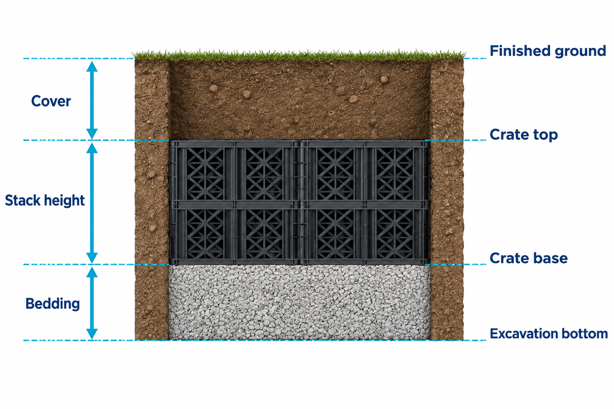
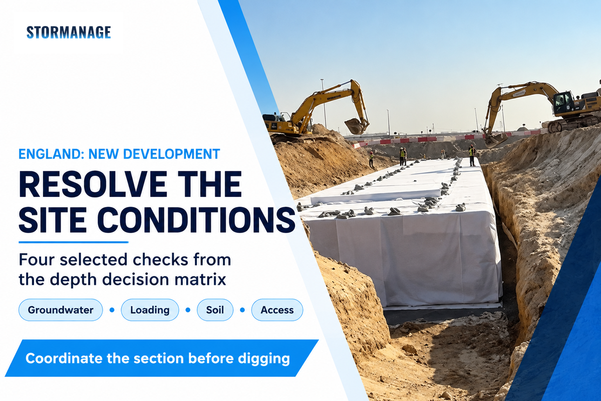
Soakaway crates need enough cover for the specified product and surface loading, plus space for the crate stack and its bedding. Determine the bottom of the excavation by adding together the three thicknesses. Groundwater, soil conditions and the drainage pipe level must also suit that arrangement.
When figuring out how deep to bury soakaway crates, start with the specific system’s installation drawing. This guide to soakaway crates then helps align the designer, groundworker and crate order around a shared depth measurement.
Before setting the dig level
Minimum cover is measured to the top of the crates; excavation continues below their base.
Vehicle loading includes maintenance equipment as well as parked cars.
A deeper pit can reduce groundwater clearance even when it provides more storage.
Confirm the proposed base level with the infiltration test and drainage layout.
How deep should soakaway crates be buried?
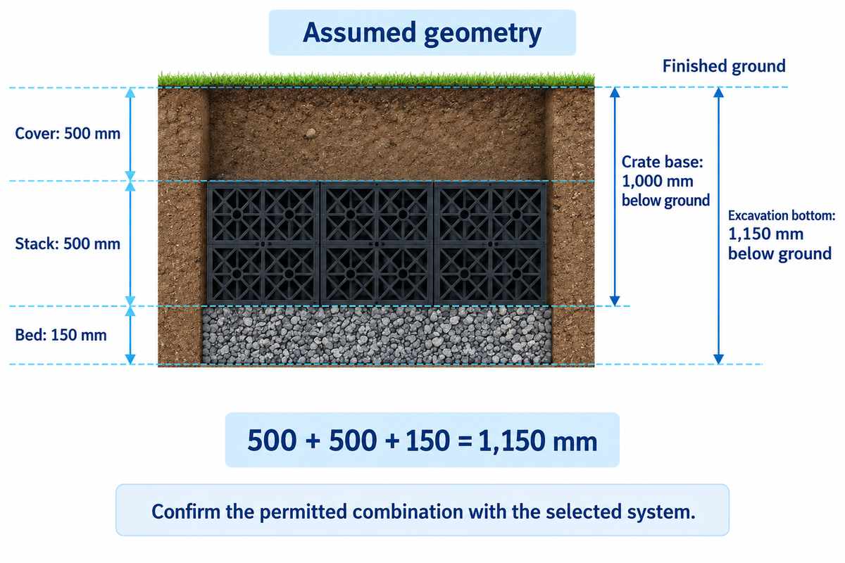
An assumed 500 mm cover, 500 mm installed crate height and 150 mm bedding give an excavation depth of 1,150 mm below finished ground. Cover is measured from finished ground to top of crate stack; stack height runs from crate top to base; bedding runs from that base to the excavation bottom.
Mark three levels on the section drawing: crate top, crate base and excavation bottom. One more mark, the drainage pipe invert, controls the point at which the water enters the drain. Horsham’s soakaway design guidance says storage depth is measured below the drain invert; cover over plastic crates from finished ground level is measured to crate top.
The chosen depth for a soakaway must accommodate both measurements.
Consider a garden where a contractor calls a 500 mm tall crate a “half-metre soakaway”. That describes the module, not the finished dig. Order a section that shows the full build-up prior to fixing the excavation level.
A later increase in paving thickness must be coordinated within the specified cover, rather than added twice.
Modular storage cells are also known as soakaway crates. Their hollow structure stores runoff while it passes into suitable ground; it is not an alternative use for plastic milk crates. For a simple guide to the storage structure itself, see geocellular stormwater storage: cells and water paths.
Garden and driveway cover: compare the exact system
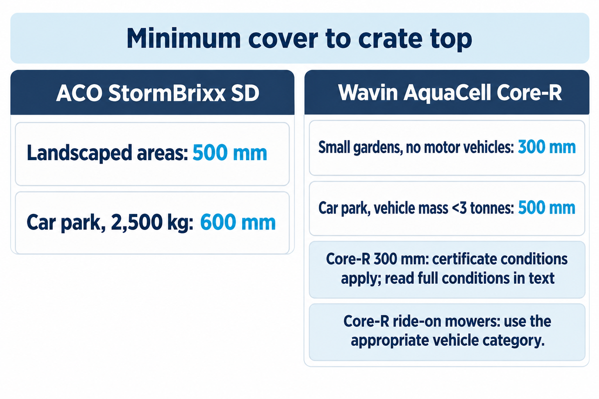
Published minimum cover can range from 300 mm for a particular small-garden installation inaccessible to motor vehicles to substantially greater depths under traffic. Refer to the actual model number by manufacturer, vehicle type and assumptions used, below. Access cover’s load class doesn’t determine the strength of buried crates.
The figures below come from the manufacturers’ own product information, rather than a common design specification.
Published minimum cover to crate top, for the stated product and use
Product
Surface use or vehicle mass
Minimum cover
ACO StormBrixx SD
Landscaped areas
500 mm
ACO StormBrixx SD
Car park, 2,500 kg
600 mm
Wavin AquaCell Core-R
Small gardens or landscaped areas inaccessible to motor vehicles
300 mm
Wavin AquaCell Core-R
Car park, vehicle mass below 3 tonnes
500 mm
Wavin AquaCell Core-R
Car park, vehicle mass below 9 tonnes
600 mm
Wavin AquaCell Core-R
Car park, vehicle mass below 12 tonnes
700 mm
Wavin AquaCell Core-R
Low-speed road, vehicle mass below 60 tonnes
1,110 mm
Sources: ACO StormBrixx SD product page and Wavin AquaCell Core-R data sheet. Wavin directs ride-on mowers to the appropriate vehicle category; the landscaped figure shouldn’t be carried across automatically. The 2020 Core-R certificate, clause 7.11 and Table 8, limits its 300 mm example to individual-house roof drainage beneath small gardens inaccessible to motor vehicles, at least 5 m from the building, in sandy gravels with surrounding-soil friction angle at least 30° and groundwater at least one metre below the units; check the full certificate and current product instructions for the remaining design conditions.
The maximum installation depth must be verified separately. Wavin quotes it to the bottom of units. In its stiff-clay example, the stated soil weight is 20 kN/m³ and friction angle 24°; the landscaped maximum is 3.85 m.
The sheet also describes the assumed ground conditions: horizontal ground, no shear planes or other soil weaknesses, no groundwater below the units, and a friction angle confirmed by a chartered geotechnical engineer allowing for clay softening during installation. Infiltration testing determines the clay’s hydraulic suitability separately from the structural calculation.
For a car park purchase, put the design vehicle, pavement section and final levels on the enquiry. Our heavy-duty soakaway crate range is a starting point for that enquiry; select the buried assembly against its structural design, including construction loads.
Calculate excavation depth with the 3-Datum Depth Stack
Excavation depth equals cover plus installed stack height plus bedding thickness: D = C + H + B. Enter the cover and bedding required by the selected installation, and use the assembled height, including any specified base or top components.
The following nine calculations all assume a 150 mm bed, the cover and stack heights shown. They compare geometry; take the permitted combination from the chosen system’s design before using a row as a dig instruction.
Assumed depth inputs and calculated excavation bottom
Cover C
Stack H
Bed B
Total D below finished ground
300 mm
400 mm
150 mm
850 mm
300 mm
500 mm
150 mm
950 mm
300 mm
800 mm
150 mm
1,250 mm
500 mm
400 mm
150 mm
1,050 mm
500 mm
500 mm
150 mm
1,150 mm
500 mm
800 mm
150 mm
1,450 mm
700 mm
400 mm
150 mm
1,250 mm
700 mm
500 mm
150 mm
1,350 mm
700 mm
800 mm
150 mm
1,650 mm
In the middle row, the crate base sits 1,000 mm below finished ground, while the excavation bottom sits 150 mm lower. Mark both levels on the drawing so that the excavator doesn’t use the crate-base level as the bottom of the pit.
Check module dimensions and assembly components in the assembled-height specifications for the selected kit. Cubic metre soakaway sets state a volume, not a dig level.
A kit labelled 1 cubic metre may describe either its outer volume or available storage; the design needs the volume basis stated for that kit.
Keep the soakaway base above seasonal groundwater
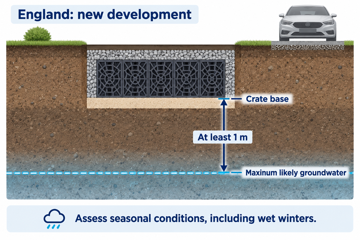
England’s national standards for new development require at least 1 m of unsaturated ground between the infiltration base and maximum likely groundwater level. Assess seasonal variations, particularly during wet winters, when setting that level.
Deeper storage lowers the infiltration base, so check groundwater clearance before accepting a taller crate stack or lower inlet.
The National standards for sustainable drainage systems, clauses 1.15 and 4.16, set that groundwater separation. A dry trial pit on one visit does not establish the maximum likely water table. Determine the seasonal condition for a new soakaway before choosing the crate-base level.
Can a Soakaway Be Too Deep?
Yes. A deeper soakaway can approach groundwater, enter a less permeable layer or exceed the assembly’s structural installation limit. Test the soil at the intended infiltration depth. Hastings’ soakaway advice calls for a trial pit representing the anticipated full-size soakaway depth below the drain invert.
Clay is a hydraulic question as well as a structural one. England’s standards say point infiltration below 1 × 10⁻⁶ m/s shouldn’t be the sole means of draining all runoff:
“shall not be fully relied on to discharge all runoff”
Design pollution treatment measures for the runoff from parking areas. The Environment Agency groundwater source protection zone guidance lists drinking-water sensitivity as a stand-alone issue. Sufficient depth clearance alone doesn’t resolve contamination risk.
Select a site suitable for a soakaway, then determine the number of modules required.
Shallow and wide or stacked and deep?
A shallow, wider arrangement can raise the crate base while retaining the same nominal storage volume, if the product permits that layout. Compare its footprint, inlet level and surrounding soil with a stacked alternative.
Same storage doesn’t necessarily mean same infiltration performance, as the base level and ground contact differ.
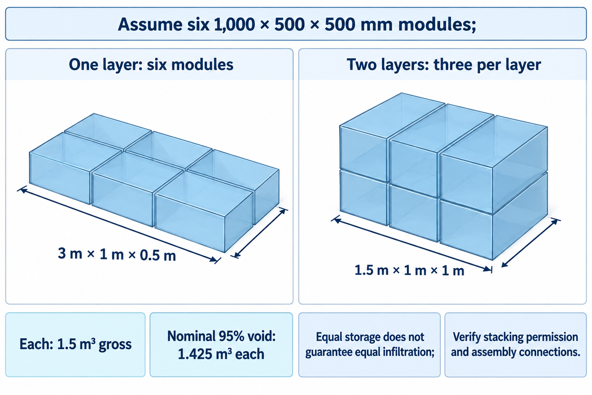
Let’s say we have six modules 1,000 × 500 × 500 mm, as shown on our soakaway installation page. At the stated nominal 95% void ratio, their 1.5 m³ gross envelope gives 1.425 m³ of nominal void storage. The sample configurations below use those same six modules.
Arrangement
Assembly footprint
Stack height
Gross volume
One layer, six modules
3 m × 1 m
0.5 m
1.5 m³
Two layers, three modules per layer
1.5 m × 1 m
1 m
1.5 m³
For a constrained garden, the stacked option saves plan area but lowers the base by 0.5 m at unchanged cover. For a site approaching its groundwater limit, the single layer deserves hydraulic review first. Verify stacking permission, assembly connections and the test at the proposed base level before selecting either option.
Susdrain’s soakaway guidance separates storage capacity from the surrounding soil’s ability to dispose of water. The surface area in contact with permeable soil also belongs in the hydraulic comparison.
Soakaway crates work by providing storage while water can soak away through the surrounding ground. Start the number of crates with the required design storage; our whole-crate quantity guide explains rounding the order to complete modules. Co-ordinate soakaway size with the inlet and the proposed level of infiltration.
Install the bedding, geotextile and backfill
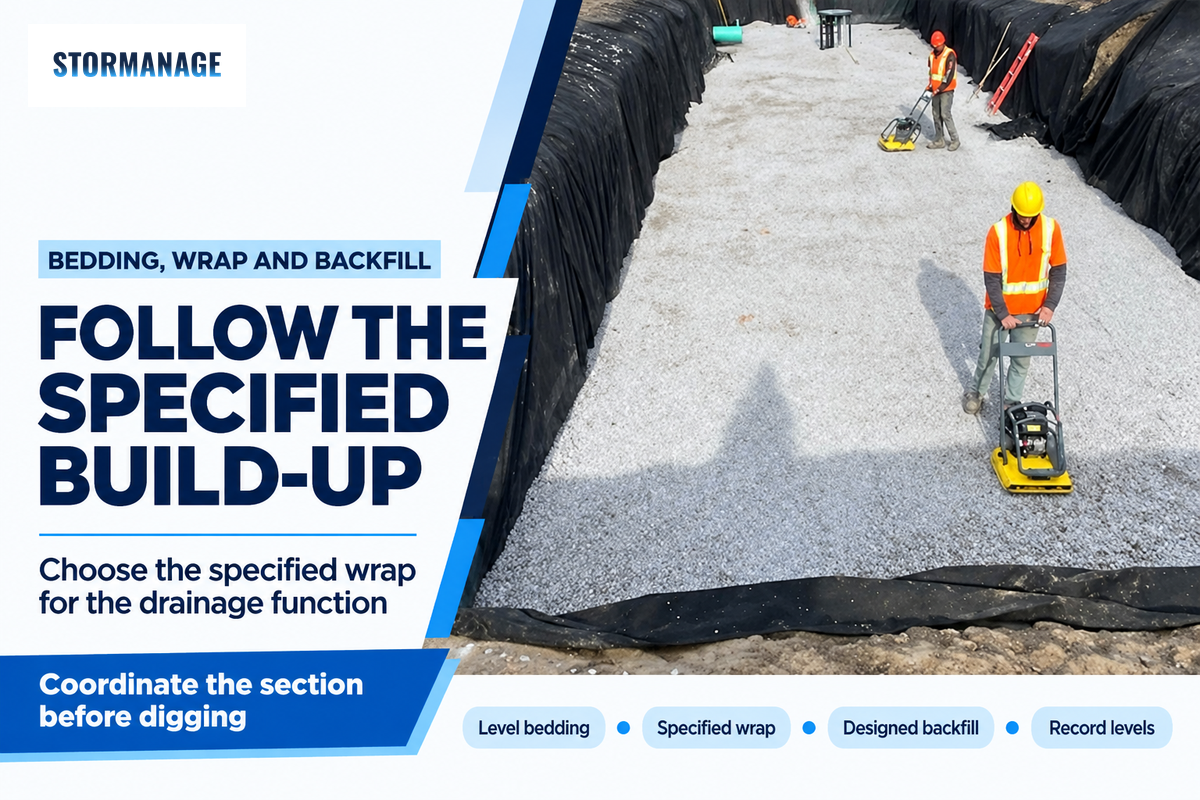
Lay the required level bed, assemble and connect your crates, wrap the infiltration assembly and place the designed backfill prior to reinstating the surface. Our installation page specifies at least 150 mm of compacted bedding, using a layer of sharp sand or pea gravel. Use the product drawing for compaction and construction loading.
The Health and Safety Executive’s excavation guidance calls for temporary support to be planned before digging. Approval of a completed car-park scheme doesn’t provide an excavator with the go ahead to move adjacent to an unsupported hole.
What goes on top of soakaway crates?
The specified permeable wrap, protective layers, structural backfill and surface build-up go above an infiltration crate assembly. Count the complete approved cover from crate top to finished surface. A garden finish and a paved driveway have different build-ups; include their layers within the design rather than adding a second generic cover allowance.
Geotextile membrane around an infiltration system lets water reach the soil while limiting soil entry. The wrap helps stop soil particles from being washed into the storage cells, where they can obstruct the voids. Use the specified material and joint details. Our attenuation design and installation guide distinguishes that permeable wrap from an impermeable geomembrane used to store water for controlled discharge. Choose the drainage function before ordering the membrane.
Use the manufacturer’s connectors or specified ties to hold the crates in position; do not substitute cable ties unless the product drawing specifies them. Assemble individual crates using the designated connection points. The infiltration assembly is wrapped in a non-woven geotextile, with the specified laps covering the outer faces of the crates.
Wrap the crates without blocking the designed inlet or access arrangements.
Where the product has pre-formed knockout sections or pipe entry points use the connection position indicated in its drawing. Insert the pipe through the designated connection and seal the wrap around the pipe as specified. Use pipe and tape only as specified for the indicated inlet connection, and support the outside of the pipe as shown on the selected product’s installation drawing.
Record the installed levels before backfilling.
For placement, gradually lower the crates using the agreed handling method. Avoid setting crates down on top of an uneven bed. The 2019 Builders’ Merchants News installation feature separates bedding, wrapping, backfill and reinstatement into distinct tasks and includes a video demonstration. Use a product-specific soakaway assembly instruction video alongside its installation drawing when checking connectors.
When planning to install soakaway crates beneath paving, agree the surfacing method first. A proposal to install permeable paving needs coordination with the whole surface water drainage system. Do not change the specified finish after the wrapped crates have been lowered without checking the cover and loading again.
Compare excavation quantities and installed-cost scope
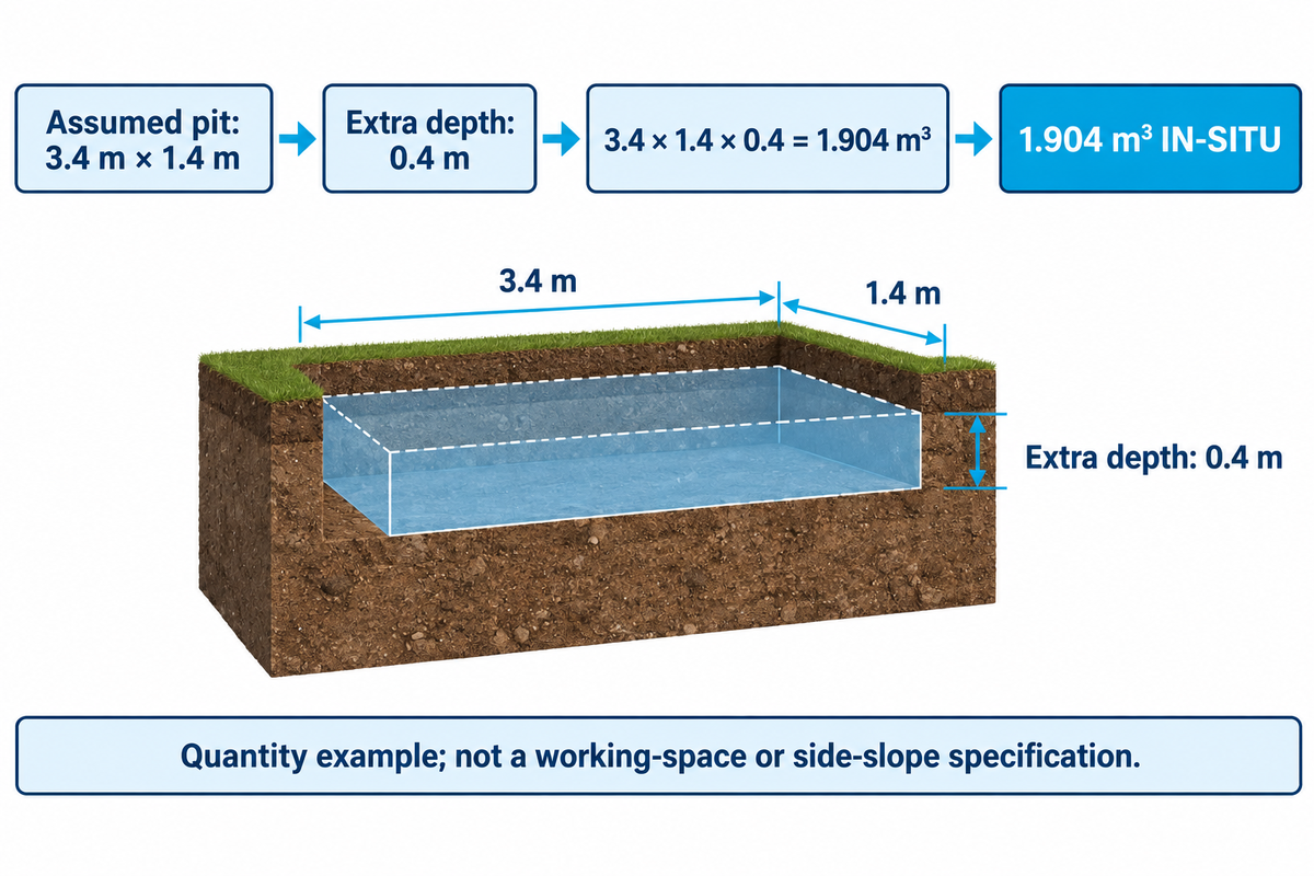
For a constant pit plan area, the extra excavation volume equals that area multiplied by the increase in depth. For an assumed 3.4 m × 1.4 m pit, an extra 0.4 m adds 1.904 m³ of in-situ excavation. Get an installed quotation independently and with support, spoil management, backfilling and surface reinstatement costed to the same scope.
The assumed footprint is a quantity example, not a specification for working space or side slopes. Loose excavated spoil volume isn’t the same as in-ground soil volume. Haulage, disposal conditions and groundwater management need project allowances rather than a fixed price per extra metre of soakaway depth.
If you need to dig a hole through an existing driveway, include removal and reinstatement of that surface when comparing prices. For two otherwise similar quotations, ask both contractors to use the same finished level, crate-base level and excavation bottom. A crate-supply price and a fully installed rainwater soakaway price cover different work.
Ask a drainage company to identify any exclusions before accepting its installed price. Compare these line items:
Site access, excavation method and temporary support.
Groundwater measures and unsuitable material removal.
Crates, bedding, wrapping and pipe connections.
Backfill, compaction and the agreed finished surface.
Inspection access, pretreatment and handover records.
Cost guides can identify scope drivers; the available Checkatrade soakaway cost guide includes depth and pipework among the complexities. Send the section and quantities with an installation-specification enquiry so the crate offer can be reconciled with the groundworks offer.
What England’s drainage standards change before you dig
England’s drainage standards, published on 19 June 2025, address new infrastructure and development on greenfield and brownfield sites. Consult your local planning & building-control standards – standards weren’t drafted as a universal retrofit installation-guide for all domestic soakaways in the UK.
East Sussex County Council’s update confirms that publication and development scope. Resolve the planning, building regulations and drainage approval routes applicable to the project. The national standards require structural integrity under anticipated loads and consideration of soil saturation. They also require an instability assessment for point infiltration within 5 m of buildings, roads, embankments or other infrastructure, with mitigation where needed.
A 5 m rule of thumb shouldn’t replace a ground-risk assessment. Susdrain’s SuDS close to buildings fact sheet explains the difference between shallow infiltration and concentrated infiltration at depth. The British Geological Survey Infiltration SuDS map separates infiltration potential from groundwater and instability hazards, including soluble rocks and artificial fill. Use that mapping for screening, followed by the necessary site investigation.
Burial-depth decision matrix: assign the next action
Condition found
Decision before excavation
Owner
Base approaches seasonal groundwater
Reassess base level or drainage arrangement
Drainage designer
Test represents a different depth
Obtain representative infiltration evidence
Drainage designer
Cars, mowers or delivery traffic cross the site
Select the applicable load and cover category
Designer and supplier
Deep stack or weak ground is proposed
Check maximum unit-base depth and soil assumptions
Structural designer
Inlet invert conflicts with the stack
Coordinate pipe gradient and operating storage levels
Drainage designer
Plant operates near the excavation
Plan support, access and construction sequence
Groundworks contractor
Paved runoff or a sensitive groundwater source is present
Resolve pollution treatment and infiltration suitability
Drainage designer
Soluble rock, fill or instability risk is identified
Obtain the required geotechnical assessment
Geotechnical specialist
Access points would be buried or obstructed
Coordinate inspection and maintenance access
Designer and asset owner
Frequently Asked Questions
Do you fill soakaway crates with gravel?
No. The designed void inside a soakaway crate provides water storage.
Fill and bedding materials belong where the installation drawing specifies them around or beneath the assembly. Putting gravel into the storage cells changes the available capacity and can obstruct access. A traditional rubble-filled soakaway and a modular plastic crate system therefore need different quantity calculations. Check the specified sand or gravel grade, placement and wrap detail before ordering either material.
Where can I build a soakaway?
Choose a location with suitable infiltration conditions, groundwater separation and acceptable effects on nearby structures and water quality.
The right soakaway location also needs a workable route from the gutter or other surface water collection point. Ground space alone is insufficient. Review the soil type, buried services, access and maintenance arrangements with the designer. Local authorities may require particular investigations or submissions. For a new build, coordinate the soakaway system with the wider development plan before fixing the excavation position.
How Far Should a Soakaway Be From Your House?
Check the local requirements; guidance commonly uses 5 metres as a starting distance from buildings.
Horsham’s guidance gives that siting distance for buildings and boundaries. England’s national standards also call for instability assessment where point infiltration is within that distance of buildings or other infrastructure. Ground conditions can justify a different design response, including greater separation. Measure the relevant infiltration feature on the layout and ask building control or the drainage designer to resolve site-specific constraints.
Can I Dig a Soakaway Myself?
Only undertake work that fits your competence and a suitable excavation plan. Buried services, collapse, access and plant loads need assessment before digging. Use a qualified drainage or groundworks contractor where installing the soakaway requires specialist equipment or temporary works.
Do I Need a Percolation Test Before Installing a Soakaway?
Obtain a representative infiltration test for the proposed soakaway design rather than selecting a depth from the crate size alone.
The drainage designer uses the test to assess whether the ground can accept the intended runoff and to calculate the size of a soakaway. Carry out a soil percolation test at the proposed infiltration level under the applicable method. An unrelated level can describe a different soil layer from the one receiving the water. Hastings’ advice specifically relates trial-pit depth to the anticipated soakaway depth below the drain invert. Keep groundwater observations separate from the infiltration-rate result, and retain the test record with the design. The procedure and acceptance requirements should follow the applicable local guidance and design method; a quick bucket test can’t replace those requirements.
Coordinate the crate order with the excavation section
Send us the required storage, proposed layout, cover, traffic and ground assumptions. We can identify the Storm Manage crate specification to take forward with your project designer.
Technical basis: this guide combines publicly available England drainage guidance with attributed manufacturer examples. The Project drainage and the structural design define the levels of installation and the allowed method of assembly and construction.