We use the details you submit to review and respond to your project enquiry. Entries are handled in this website’s WordPress database using Fluent Forms; our hosting and email providers may process the submitted details. Other technical providers receive only the data described in our Privacy Policy.
Please do not send passwords, payment-card details, government identification numbers, sensitive personal data, or unnecessary confidential third-party information.
National Standards for SuDS, Standard 7 (non-statutory)
Wales statutory SuDS approval
Flood and Water Management Act 2010, Schedule 3 (since 7 Jan 2019)
Heavy-Duty Soakaway D400 is a labeling shorthand that pairs a D400-rated surface component with a buried geocellular attenuation or infiltration crate; on its own, the rating never certifies the buried tank underneath. If you set out to find one, the chances are that one question has been posed above all others – will that buried tank withstand the weight of traffic loading passing above it? Simply stating ‘D400’ won’t answer that question – that designation comes from standards developed for surface-level drainage, not buried geocellular storage. What actually does the D400 designation certify? How does load get down to the formation layer through the other layers above it, and what seven-item ‘evidence pack’ can any drainage designer, structural engineer or estimator expect before submittal sign-off?
Answer: A D400 rating on a soakaway crate borrows a surface-hardware classification, BS EN 124 covers or BS EN 1433 channel drainage; it does not certify the buried tank. Confirm the crate’s own structural standard (BS EN 17152-1, CEN/TS 17152-4, CIRIA C737) before treating “D400” as buried-system proof.
D400 is a surface-component class, not a buried-system certification.
BS EN 124 (covers & gratings, 400kN) and BS EN 1433 (channel drainage, 40t) are both D400 product standards.
D400 rated crate under BS EN 17152-1:2019 and CEN/TS 17152-4:2024, referenced against CIRIA C737.
Load passes through at least five layers of the structure on the way down to the crate.
Seven items ‘evidence pack’ before the load claim enters the design calculation for your drainage.
Start with the D400 Label Split
‘D400’ isn’t the full rating for a buried storage tank for soakaway systems. It only identifies the rated surface components in conjunction with an associated standard number.
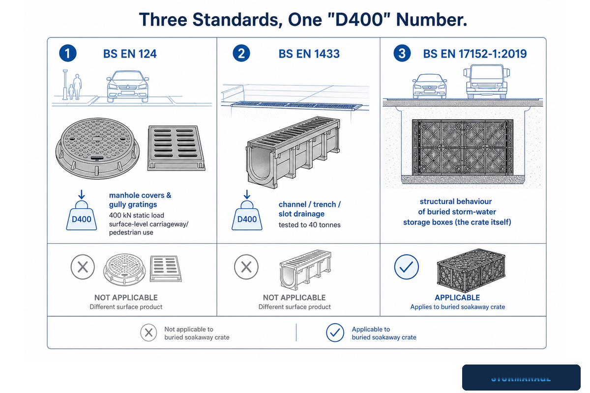
Search results for that precise terminology currently blend two completely unrelated products under a shared load-class number. Our CIRIA guide to modular geocellular systems explains that a mix-up has arisen from two independent British and European standards, which separately but coincidentally designate ‘D400’ as their equivalent load-class number: the first, BS EN 124 covers manhole covers and gully gratings which are load tested to a 400 kN static load, and are designated for surface level loading in both vehicular and pedestrian carriageways, hard shoulders and parking areas. BS EN 1433 covers channel drainage, sometimes marketed as slot drain or trench drain – the linear grated channels that are used along road verges, roadsides or in high-traffic parking spaces – which are tested to 40 tonnes separately for its purpose. Therefore, a channel/trench/grate/grating carrying a BS EN 1433 D400 designation is not the same as a D400 load-rated buried storage crate. Neither BS EN 124 nor BS EN 1433 classifies or certifies a buried geocellular soakaway crate.
Each crate has its own specialised third standard. BS EN 17152-1:2019 provides requirements for structural behaviour of storage boxes for storm-water which are made of PP and/or PVC-U, and in scope includes units intended for underground use such as in landscape, pedestrian or vehicular traffic areas, as part of a modular system where the manufacturer specifies how the system elements are assembled. A technical specification document, CEN/TS 17152-4:2024, covers calculation procedures for these buried geocellular modular storage systems, including the equations and vehicle live loading to determine installation size and capacity. Neither of the two above ‘D400’ standards are featured in CEN/TS 17152; the crate is not unrated – merely rated according to a different system for its intended use.
D400 Label Split
D400 Label Split: give the standard and tested surface behind a D400 claim, before taking the class number as fact of what buried crate capacity is.
⚠️Important
A product page for a buried crate will just give D400, without specifying it has been produced to BS EN 17152-1, CEN/TS 17152-4, or CIRIA C737: therefore it has not yet told a reviewer which, if any, standard was used as the basis for design of the buried system.
This is broader than just the two standards above; however, a consumer search under ‘D400 buried crate’ also brings up the similar specifications ‘D400 drainage channel’, ‘drainage channel’ or ‘French drain channel’, all referring to the same BS EN 1433 category under the guise of regional or street level names, and not describing a buried crate. Materials differ too: BS EN 124 covered manholes and gratings tend to be manufactured from steel or iron and placed into the top of a concrete surround, rather than the PP/PVC-U geocellular-type crate under a paved foundation.
The Buried Tank Needs a Different Proof Chain
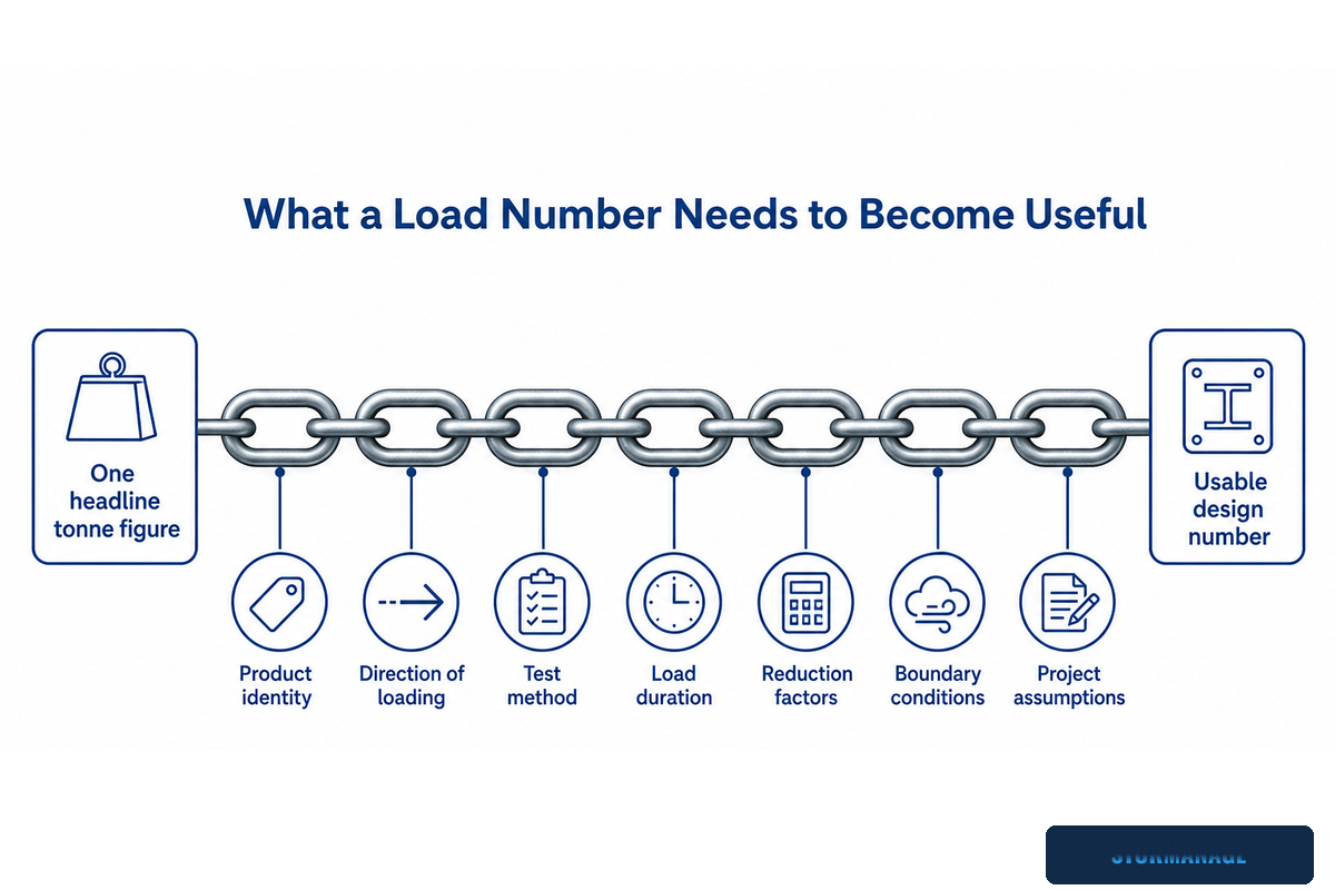
One headline heavy-duty tonne figure is an indication only, not a design parameter. Designing a structural buried drainage system into place can’t be a ‘DIY’ design process, and for a number to be of practical use to a designer it requires a product identity, direction of loading, test method, load duration, reduction factors, boundary conditions and project assumptions added to it. Anyone specifying or considering the loading requirement for industrial vehicle yards and street-level car parks would expect the crate to carry the load without failure, but would do so with a product that had a proven design life basis for the expected loading.
CIRIA C737, the currently referenced guidance (superseding earlier C680), covers both structural and geotechnical design guidance and testing for geocellular drainage systems (materials required, design testing and excavation). CIRIA C753, the SuDS Manual, which cross-references CIRIA C737’s requirements in its geocellular storage chapters, includes structural design as an element within the wider design process for the SuDS. Any product test report with a peak load capacity without a stated test method, load direction and design life basis may well be less useful than first thought, given that the word ‘durable’ must reflect the underlying basis.
A reviewer must be clear on what standards and methods have been applied to obtain a load capacity, and on which element, and under what conditions has load testing taken place (product and its exact geometry, load direction, duration and applied reduction factors for design life). On its own, a capacity figure will be insufficient for designers and engineers.
Standards Classification Matrix: which class/type of standard each reference below governs, so a reviewer does not mix a surface-hardware class with a buried-structure design procedure.
Standard
Class/Type
What it governs
BS EN 124
Surface-hardware class (D400, 400 kN)
Covers and gratings for vehicular and pedestrian carriageways
BS EN 1433
Surface-hardware class (D400, 40 t / ≈392 kN)
Channel/linear drainage systems — not a buried tank
BS EN 17152-1:2019
Product standard
Storm-water storage boxes in PP/PVC-U, buried underground use
CEN/TS 17152-4:2024
Design procedure
Structural design of buried modular systems under vehicle surcharge
CIRIA C737 (supersedes C680)
Design guidance
Structural and geotechnical design of geocellular systems
CIRIA C753 (SuDS Manual)
Design guidance
Frames structural sizing as one input into the full SuDS process
BS EN 17150:2019
Test method
Short-term compression strength
BS EN 17151:2019
Test method
Long-term compression strength
National Standards for SuDS (2025), Standard 7
Regulatory guidance (non-statutory in England)
Structural loading and saturation-weakening requirements
Flood and Water Management Act 2010, Schedule 3
Statutory requirement (Wales only, since 7 Jan 2019)
Mandatory SuDS approval for qualifying developments
Trace the 5-Layer Load Path
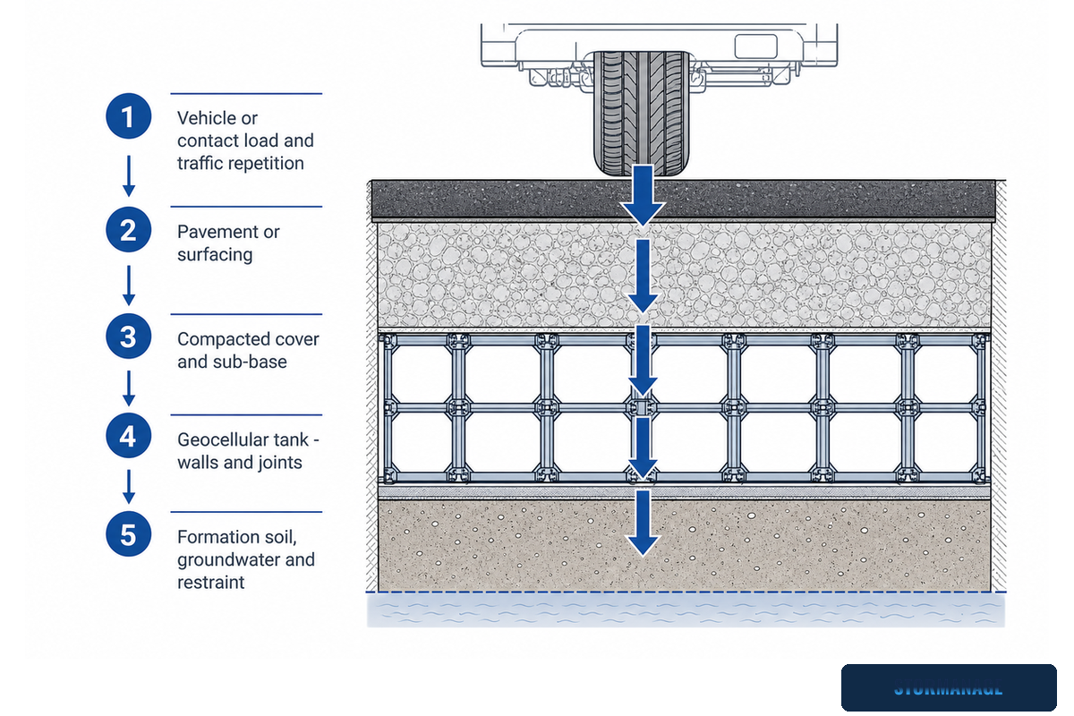
It must be understood that load doesn’t land directly onto the crate – but is conveyed through the surface finish, cover, the subbase, the tank’s lateral and internal wall, the end of the wall interface into the ground on which it’s founded.
The five layers a wheel load crosses before it reaches a buried soakaway crate, with the responsible party for each layer’s design input.
The five layers, in load order
Vehicle or contact load and traffic repetition.
Pavement or surfacing.
Compacted cover and sub-base.
Geocellular tank itself, and its joints, wall interfaces.
Formation soil, groundwater and restraint.
5-Layer Load Path
5-Layer Load Path: a wheel load lands the paving slab, then the cover system, the base course, the end wall / shoulder of the tank and into the ground in which it’s founded.
Lateral load on buried crates is treated as a value from calculations with data being multiplied up by a factor relating the degree of plasticity of the back-fill used. For instance, installation with 2 different back fills can yield differing load calculations. It’s the quality of installation for the wrap and connections that must be checked to the spec, not that geotextiles and connectors were delivered.
One problem is that 5 out of 6 of the design calculation’s “input” numbers aren’t on the data sheet. Any review which proposes giving a product a “duty” should at least be able to name one of these 5 values, let alone all of them, apart from the one illustrated on the crate. This layer-by-layer transfer of load into the surrounding ground, rather than onto the crate module in isolation, is exactly the mechanism CIRIA’s geocellular storage systems guidance describes for buried attenuation and infiltration structures.
“When a submittal shows only one tonnage figure, we ask for the test method and load direction behind it before anything else. A number without those two facts doesn’t tell us whether the crate will hold under a loaded skip lorry or a fire engine.”
📏 Engineering Note
Patent-approved lateral load factors on a buried geocell go from around 0.20 for sand type backfill to 0.3 – 0.4 for back fills such as quarry and demolition waste, with their associated plasticity. This value is a factor based on input on to the load, not a constant, with the specified back fill of the actual installation on any site. This is alongside two sets of test loads which quite often confuse both consultant and installer, i.e. BS EN 124 covers and gratings with its load-bearing capacity of 400 KN static loads, and the BS EN 1433 channel range with its 40 “tonne” load class. Neither of which is a full certification or otherwise of the buried structure itself, and for that matter are both from separate product standards.
Separate Short-Term, Long-Term and Lateral Checks
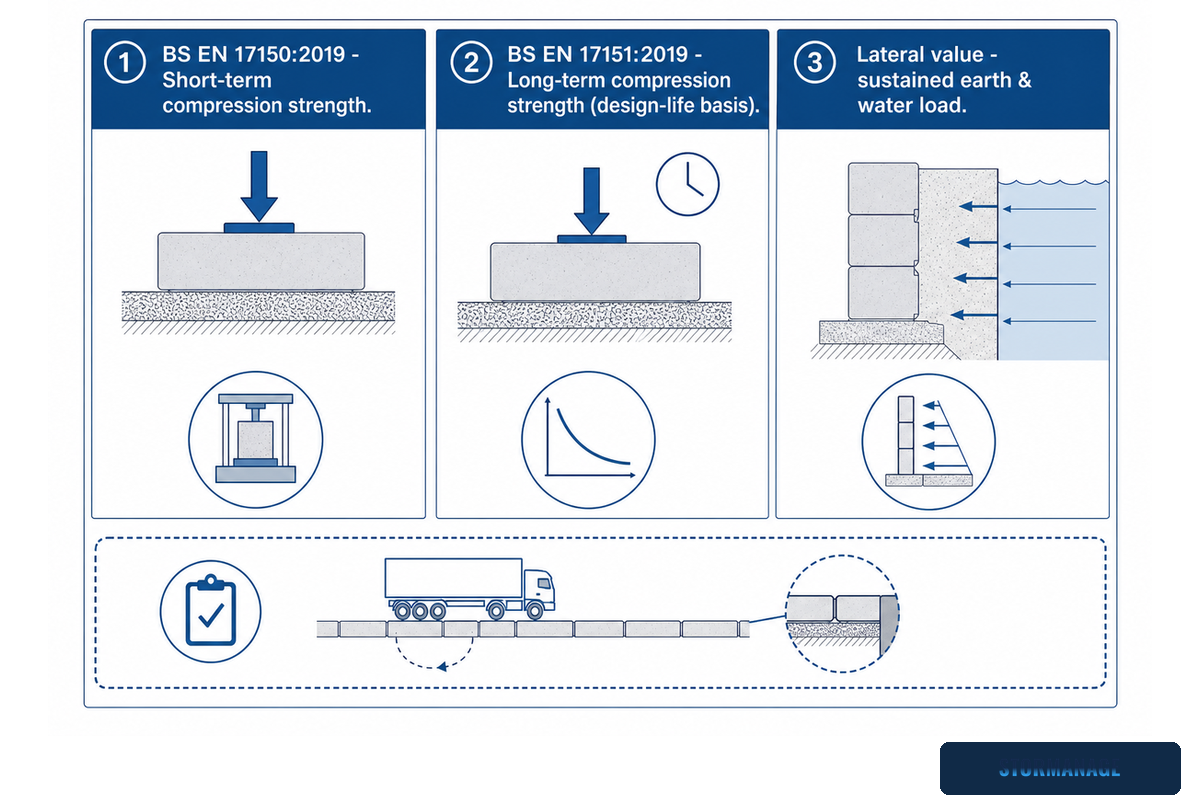
Often the largest number printed on a data sheet isn’t always the most useful in a specific design context or in many, many cases, not the one you need if the direction or duration in which the load is applied is wrong!
These European test-method standards deliberately keep the two separate: BS EN 17150:2019 covers the short-term compression strength test whereas BS EN 17151:2019 defines the long-term compression strength test – two distinct, mandatory tests rather than one ultimate number extrapolated forward. Build-time, or short-term vertical compression, value of a crate’s plastic is different from its long-term Design-Life value, and neither is comparable to its Lateral value under sustained earth and water load. Traffic repeat loading and the condition of joints and edge interfaces add a further check on top of these three! Any comparison-table which assigns one “Capacity” figure without segregating these into the required categories has in effect conflated five different, unrelated numbers into one misleading “capacity” designation. Some manufacturers publish headline Design Lives of 50 to 100 years based on Accelerated Creep Tests, but that range isn’t one number for every use: lightly loaded areas such as car parks and domestic driveways get an achievable design life of 50 years, while designs subjected to frequent heavy-goods-vehicle traffic are typically limited to a 25-year Design-Life (British Plastics Federation Pipes Group). This short-term/long-term split is standard practice for buried polymer structures generally: published engineering test data for geocellular modular units shows design safety factors typically sitting at 1.2-2 for temporary applications, then climbing to 2.7-5 once the application is long-term, precisely because a higher, sustained factor is needed once creep and duration are in play (US Patent 8,157,472).
💡Pro Tip
If a comparison table lists only one load figure, identify it explicitly as – short-term vertical, long-term vertical or lateral – prior to comparing it with another manufacturer’s. An unlabelled figure is not comparable to another one.
The Buried-System Evidence Pack: 7 Traceable Items
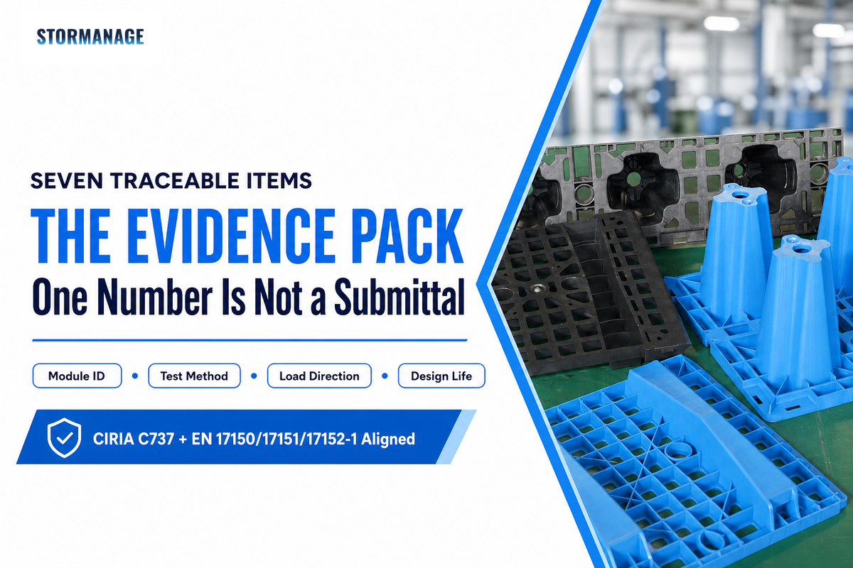
Any submittal for buried Heavy Duty Soakaway System D400 will consist of SEVEN traceability items, not a single headline figure as would generally be associated with a typical product submission; two independent technical resources – the latest CIRIA structural design guide for buried plastics pipe systems and the relevant family of Harmonised European Test-Method Standards (EN 17150/17151/17152-1) – both indicate there should be SEVEN items, so this isn’t a house format from a single supplier.
The seven-item Buried-System Evidence Pack for a Heavy-Duty Soakaway D400 submittal, with a pass/clarify/stop status column.
Item supplied
What it proves
What remains unknown
Exact module identification and geometry
Which specific product the figures below apply to
Whether a substituted or “equivalent” product carries the same figures
Standard or test method cited
Whether the figure is comparable to another product’s
Whether the test used the project’s actual conditions
Load direction and boundary condition
Vertical, lateral, or both, and under which restraint
Whether the project’s governing load matches that direction
Short-term result
Construction-stage and peak-load capacity
Long-term, service-life performance
Long-term/design-life basis and reductions
Sustained-load and creep-adjusted capacity
Whether the stated design life matches the project’s
Lateral capacity or structural model
Behaviour under earth and water pressure at depth
Whether the stated backfill material matches site material
Project check tying traffic, cover, soil, groundwater and construction assumptions together
Whether the product figures actually apply to this site
Anything not explicitly checked against site conditions
Buried-System Evidence Pack
Buried-System Evidence Pack – the SEVEN traceability items required before sign-off; Identity, Standard, Direction, short-term load, long-term load, lateral load, and project-specific review check; not one headline figure but all seven traceability components.
Our review of top search results for a given phrase didn’t reveal any site that supplied all 5 of these items in combination – a given standard with a test load/method, a long term/Design Life value, a lateral load value and a detailed installation build-up specification – but this is typical for this product class, so if your review is about to sign off and hasn’t come across any of these five items for that listed product, then request this Pack.
Cover Depth Is an Output, Not a Nickname
There’s no universally safe design depth to bury a D400 Soakaway Crate. Shallow and deeper installations fail for different reasons, and safe Design Depth relies on understanding the complete build-up and ground assumptions, not the arbitrary single number cited for the product name only.
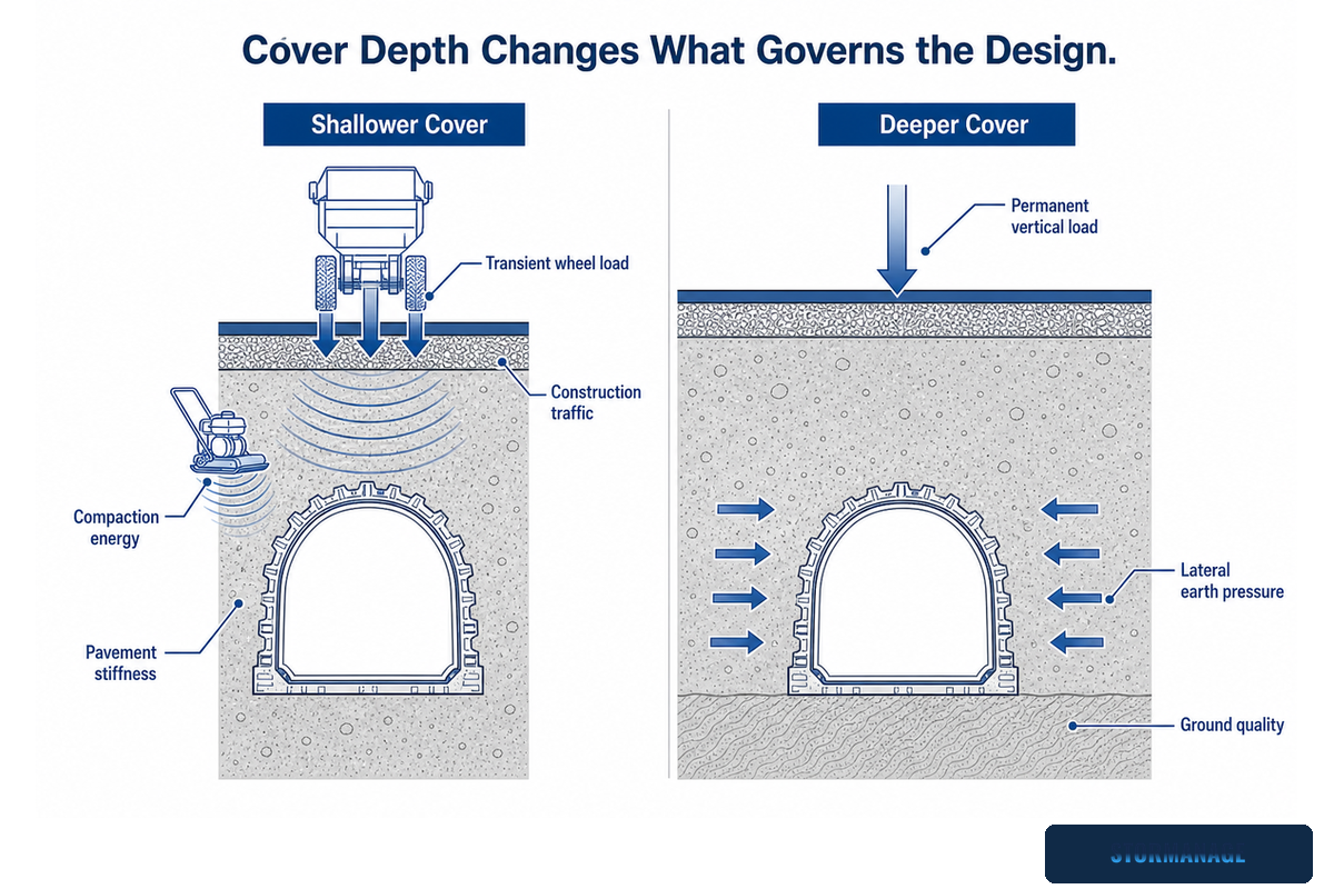
Shallower cover: shallow cover depends on transient loads from wheels, traffic during construction, compaction energy, and stiffness of the pavement over the tank. Deeper cover: the primary load become permanent vertical loading, lateral earth pressure, and ground quality; these conditions drive the requirements more heavily. The National Standards for Sustainable drainage systems recognise this in its standard of particular relevance Standard 7 ‘All materials and components shall be demonstrated to be suitable to resist all imposed design loadings with appropriate factors of safety’ (7.25) and, ‘Where infiltration systems lie below trafficked areas consideration should be given to structural loading and any likely weakening of the soil due to saturation.’(7.26). Ground that’s saturated behaves differently from dry ground and this is why a single depth value isn’t transportable between sites.
CEN/TS 17152-4:2024 details the calculation required – a procedure of precisely this kind ‘underground modular system, under vehicle surcharge loading’. It lays out sample loading data, structural characteristics and charts rather than a single number. That calculation requires you to input into the procedure the selected module and confirmed build-up of the tank system, the prevailing site ground conditions, and the resultant cover depth will be the outcome.
Depth ranges given on product data sheets or online product selectors are an input for that calculation. Storm Manage’s own load-class and cover-depth selector and soakaway crate sizing calculator are built to accommodate these project-specific inputs rather than return one fixed number.
Structural Strength Does Not Prove Hydraulic Suitability
Even a functionally sound, structurally approved tank may not be the right drainage solution for you.
Questions of how, where, and what material to use to manage attenuation/infiltration, the ground interface, surface water quality, how to manage occasional over-flows and maintenance access still stand separately from the surface-loading question.
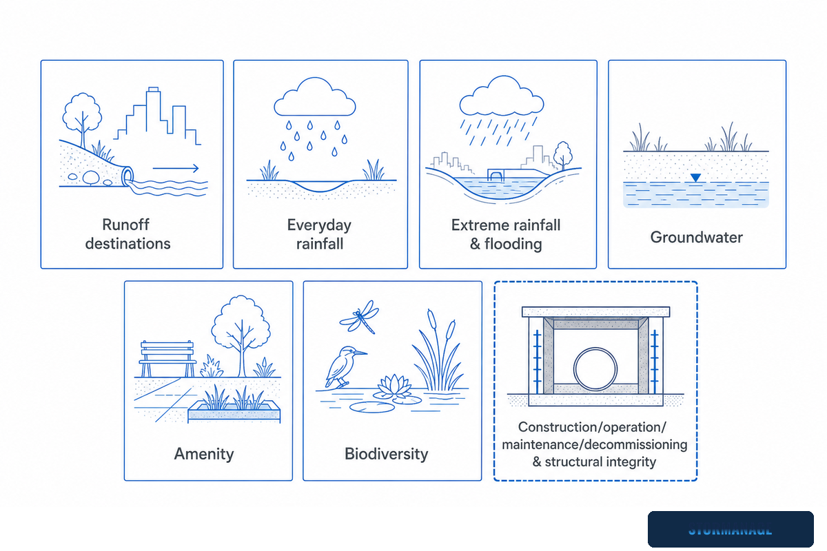
Published in 2025 and representing the first major review of national standards in over a decade, the National Standards for Sustainable Drainage Systems organise these issues as seven separate, equally important, co-equal standards for runoff destinations; management of everyday rainfall; management of extreme rainfall and flooding; groundwater; amenity; biodiversity; and design for construction, operation, maintenance, decommissioning and structural integrity. Structural integrity is one of seven standards to be assessed independently, not a single pass/fail hurdle that also ensures the satisfaction of the six remaining standards. Any crate that meets the standards for load testing, for example, will be a structurally validated product; but it won’t, for that fact alone, meet groundwater, quality or maintenance standards.
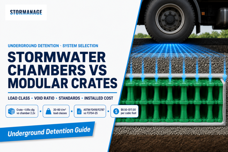
It’s by way of that difference, too, that it was decided which of the product Families was right. This ‘soakaway’ approach relies upon a permeable interface for the water in the buried void – the void – to exit into neighbouring ground, the same underlying principle behind a traditional sump or sump pit dug straight into the subsoil, just engineered into a modular crate instead of a rubble-filled hole. Meanwhile, the ‘attenuation tank’ approach relies on a secure sealed liner to retain the water in the void until such time as it can be safely discharged, and the two can share the same structural crate Family across a wide span of site conditions whilst, as we’ve just seen, having diametrically opposed functions and marketing messages, both based around D400. Storm Manage’s stormwater detention tank cost and sizing guide covers that calculation for the attenuation side of decision-making in more depth.
✔ Structural evidence alone confirms
Crate capacity covers the advertised load with the specified vertical and lateral loading components.
Build-up meets Standard 7 (structural integrity)
Joints and edges interfacing the box are taken into account in the structural design.
⚠ Structural evidence alone does not confirm
Whether infiltration or sealing liner is preferred by the specifier.
Groundwater risk or infiltration-rate suitability
Water-quality treatment, silt control or exceedance routing
Read Failure Clues as Missing-Evidence Signals
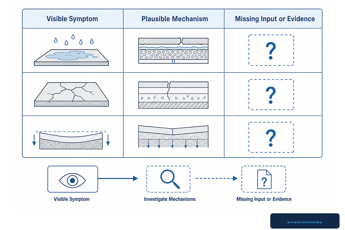
Any visible symptom over a buried system tells the project team nothing about the remote performance of the buried system; it alerts them to what should be researched and precisely which aspect of missing evidence is needed to support further analysis or a durability claim testing to a full-load cycle.
Gov.uk’s National Standards for SuDS places a clear, unambiguous requirement on design teams: “the design of the surface water drainage system should ensure that if there is a risk that blockage or clogging could cause the system to fail, then this should be apparent by visual inspection from the surface” (Requirement 7.16.1). This is a standalone requirement alongside requirements for maintenance (7.12), pre-treatment for preventing clogging (7.13) and preventing sediment build-up within the system (7.14). The design goal, thus, is to make failure-in-development a visible symptom rather than leaving maintenance teams to make the system fail and see what happens. North Lincolnshire Council’s own policy guidance on soakaway designs similarly includes regular monitoring/inspection and the removal of sediments as a permanent part of preserving a system’s function and proving it will perform.
The Red-Flag Matrix: six visible symptoms above a Heavy-Duty Soakaway D400 installation, mapped to the missing evidence each one points to.
Visible symptom
Plausible mechanism
Missing input/evidence
Immediate response
Rutting or local settlement
Cover/sub-base under-designed for actual traffic
Pavement build-up spec vs. traffic count
Request the pavement design check, not just the crate rating
Tank-edge depression
Edge/interface transition undersupported
Edge-restraint and interface detail
Check the interface detail against the installation drawing
Crate deformation or displaced connection
Load exceeded short- or long-term rating, or connector failure
Which load direction and duration governed
Escalate to a structural review before further loading
Ponding or slow recovery
Infiltration rate lower than design, or silting
Infiltration test data vs. design assumption
Investigate hydraulic performance, separate from structural
Early silt accumulation
Pre-treatment undersized or missing
Silt-trap/pre-treatment sizing
Check inlet pre-treatment against Requirement 7.13
Movement during backfilling or compaction
Backfill material or compaction sequence not per spec
Installation records for material and compaction method
Cross-check against the contractor’s inspection records
Red-Flag Matrix
Here, the ‘Red Flag’ Matrix links surface symptoms to the missing evidence needed to avoid remote diagnoses.
Record the SuDS Requirement by Country, Not by “UK”
There’s no ‘current’ single, unified British rule on what must appear on an approval dossier/file.
But what does all this tell us about Wales in particular?
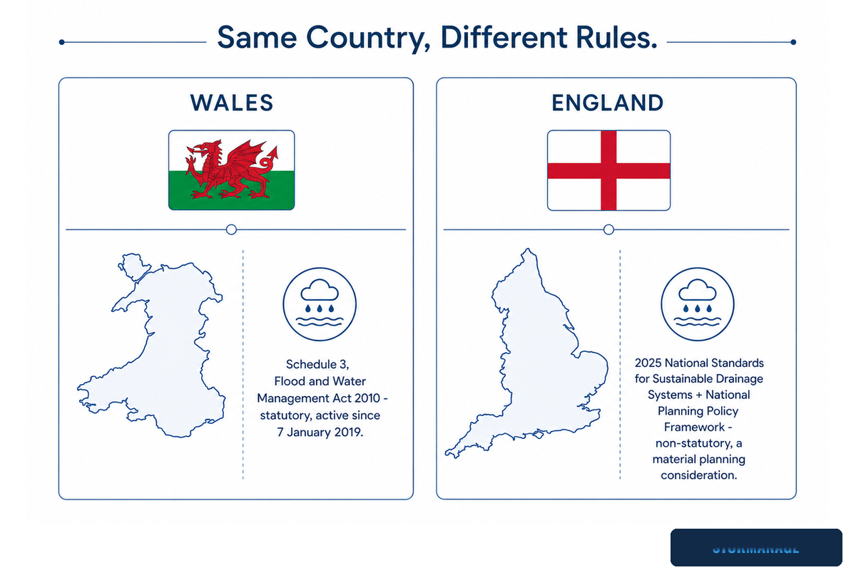
Firstly, Wales has a statutory SuDS requirement: Schedule 3 of the Flood and Water Management Act 2010 has been active in Wales since 7 January 2019 and requires formal SuDS approval for qualifying developments. But in England it’s different: the 2025 National Standards for Sustainable drainage systems and the National Planning Policy Framework don’t apply as of right (e.g., under law): they operate as a “material planning consideration,” meaning a planning authority is obligated to take them into account when deciding whether to grant or refuse an application, rather than having to ensure compliance in the same way as if they were a legally binding statute. There has been no announcement as to when, if ever, Schedule 3 will be enacted in England.
Making a note that merely says “the UK SuDS standard” without specifying the country may inaccurately reflect a non-mandatory consideration as mandatory or vice versa, and will lead to confusion.
Putting aside this legal/non-legal segregation, both countries have the same Structural Integrity and Saturated Ground issues which are considered under standard 7 (as discussed above) and both would want the Maintainability, Access to Inspection, and assumptions in the design to continue into post-handover. By country, the difference lies in which items trigger the legal approval process and the ones where the reviewer might have to consider but can’t write it as a requirement. Storm Manage’s SuDS drainage development guide details the broader development approval process in which this falls.
Complete the D400 Pass/Stop Handoff
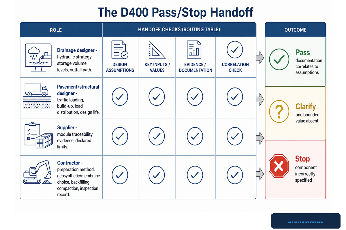
There are four distinct roles and each is responsible for one of the fragments of the evidence shown; the submittal is only really closed once all four are present. It isn’t closed when only one party has proved its fragments to everyone.
Inputs by owner
Drainage designer – hydraulic strategy, storage volume, levels, how it infiltrates and to which outfall or how exceedance path develops to outfall.
Pavement/structural designer – traffic loading, build-up, load distribution, design life and ground assumptions.
Supplier – module traceability evidence, declared limits and the input on which those declared limits are predicated.
Contractor – method of preparation, geosynthetic or membrane choice, backfilling, compacting, laying order and record of inspection.
Once all four of these are gathered, the review is narrowed to one of three results: “Pass” confirms that the documentation correlates to assumptions underpinning the project – e.g. the cited standard correlates with the product; the relevant load orientation correlates with the governing case; the build-up correlates with the design-life basis. “Clarify” confirms that one bounded, nameable value was absent (perhaps a lateral loading value was not submitted, or backfill was yet to be reconciled to the stated value). “Stop” applies where either the component is incorrectly specified (for example, a BS EN 1433 channel-drainage certificate supplied to verify a buried crate), the structural basis cannot be substantiated as being rooted in any cited standard, or the assumed in-situ conditions underpinning the supplier’s stated results conflict with the project’s ground investigation works.
Any stop here will be significantly less costly than a stop after installation. This four-way sign-off discipline mirrors the whole-lifecycle structural-integrity requirement set out in Standard 7 of DEFRA’s National Standards for Sustainable Drainage, which replaced the narrower 2015 guidance in June 2025.
D400 Pass/Stop Handoff
D400 Pass/Stop Handoff: a designer/contractor/supplier set of evidence resolves to pass, clarify, or stop and then a buried-crate submittal moves toward sign-off.
Once that handoff is cleared, then the reader can focus on product selection, sizing and procurement – the purview of Storm Manage’s own heavy-duty soakaway crate design-input page, and once the module and load direction is confirmed, its supplier spec checklist and installation guide for the build-up and construction-sequence detail a contractor needs to carry the evidence pack through to site.
Frequently Asked Questions
How much weight can a soakaway crate hold?
No crate has one universally transferable tonnage figure; useful capacity depends on load direction, test method, duration, creep and safety factors, cover build-up, ground support and underlying soil. Ask for Short-term, Long-term and Lateral load evidence before accepting any single number.
No single crate carries a universal “tonnage” figure. Safe load capacity depends on load direction, test method and duration, creep and safety factors, cover build-up, ground support and underlying soil. Ask for Short-term, Long-term and Lateral evidence, and insist on a project check that can trace actual traffic load back to the buried tank.
How deep should soakaway crates be buried?
There is no responsible universal depth; it depends on a design check tied to the chosen module, cover build-up, ground conditions, design life and build sequence. Shallower cover shifts load toward wheel and pavement stiffness, while deeper cover shifts it toward permanent vertical load and lateral soil pressure.
There’s no responsible “universal” depth. Shallower can be constrained by wheel load, pavement stiffness, compaction loads during construction and overall load from traffic while shallower levels include effects of vertical load under fill material while deeper levels will be influenced by permanent vertical load and laterally by soil pressure and any under lying soils. Use a design check that matches selected module, build-up, ground conditions, desired design life and build sequence.
Are soakaway crates legal in the UK?
Acceptance is not decided by a product nickname; it depends on the relevant national and local requirements, the accepting authority, drainage scenario, infiltration or outfall evidence, structural integrity and maintenance. Soakaway crates are statutory under SuDS approval in Wales and guidance-only in England, so the applicable requirement must name the country rather than a generic ‘UK standard’.
Crates aren’t approved by a product name only. Approval is determined by national and local requirements, the accepting authority, the drainage scenario, intended location, infiltration or outfall evidence, structural integrity, water type and durability, and maintenance. As discussed previously, it is statutory in Wales and guidance only in England; the applicable requirement must specify the country rather than simply “UK standards.”
Do you fill soakaway crates with gravel?
Modular storage voids are not filled like a rubble pit; the surrounding material and membrane depend on whether the system is infiltration or attenuation. Infiltration designs use a permeable geotextile so water can exit into the ground, while attenuation designs use a lined, non-permeable membrane that holds water until discharge; surround, bedding, ventilation and silt-containment details still follow the project specification.
In normal circumstances, the modular storage void will not be filled in the same way as a rubble pit. It will typically be constructed using materials that surround the system along with either a permeable or non-permeable geotextile layer to delineate infiltration and attenuation systems. In infiltration situations, the water can exit through permeable interface while in attenuation situation a lined liner will hold the water prior to discharge. Surround and bedding types, ventilation, inlet controls, silt containment and protection all remain factors to be addressed; Follow project detail.
What can I use instead of soakaway crates?
Alternatives depend on the drainage objective and site constraints; infiltration basins, trenches, permeable paving, storage tanks and pipe systems are not like-for-like substitutions for a geocellular crate. Compare land ownership, groundwater level, water quality, maintenance access and discharge conditions before treating any option as a direct swap.
Alternatives are governed by drainage objective and site constraints. Basins, trenches, catch basins, permeable paving, tanks and pipes each serve a different function, not direct replacements. Compare land ownership, groundwater, water quality, maintenance and discharge conditions.
This analysis was prepared by the Storm Manage technical content team to help drainage designers and specifiers separate a surface D400 classification from the structural evidence a buried soakaway system still needs. Standard citations, patent references and regulatory requirements above were checked against primary and government sources rather than taken from vendor marketing copy. Storm Manage publishes SuDS, stormwater detention, rainwater drainage, surface water drainage and highway drainage guidance alongside its drainage products and drainage supplies range, in support of efficient water management on trafficked sites; this article is educational and doesn’t replace a project-specific structural design check. Reviewed by the Storm Manage technical team.